L-band inductive output tube

a technology of inductive output tube and l-band, which is applied in the direction of transit tube circuit elements, tubes with single resonators, klystrons, etc., can solve the problems of limiting the useful frequency range of iots to frequencies below 1000 mhz, the relative length of the electron bunch formed by the low drive frequency, and the marginalization of efficiency and gain

Inactive Publication Date: 2006-12-05
COMM & POWER IND
View PDF29 Cites 4 Cited by
  • Summary
  • Abstract
  • Description
  • Claims
  • Application Information

AI Technical Summary

Problems solved by technology

However, it has long been thought that transit time effects limit the useful frequency range of IOTs to frequencies below 1000 MHz.
The main drawback to this approach is the relative length of the electron bunch that the low drive frequency forms.
Although the maximum of the current passes within the deceleration phase and thus ensures power conversion into the desired frequency, a considerable amount of electrons become accelerated, marginalizing efficiency and gain and causing problems with collector dissipation and X-ray radiation.

Method used


Image

  • L-band inductive output tube
  • L-band inductive output tube
  • L-band inductive output tube

Examples


Embodiment Construction

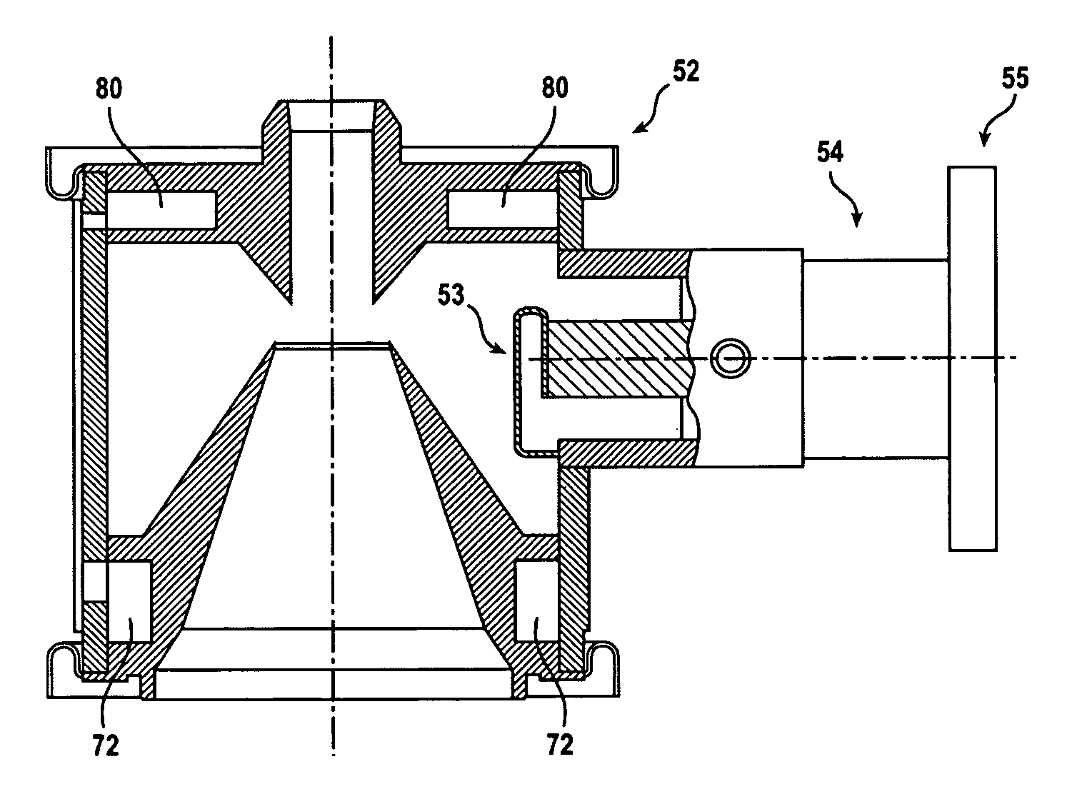
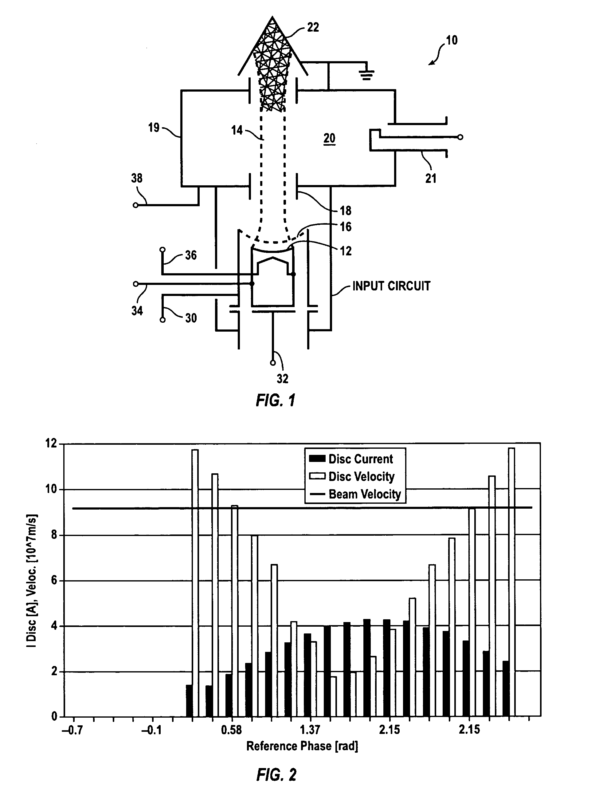
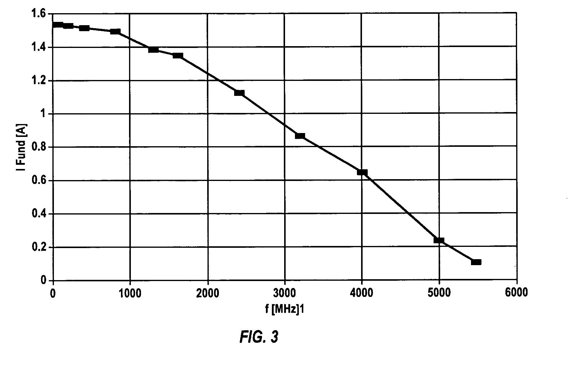
[0026]Embodiments of the present invention described in the following detailed description are directed at L-band IOTs. Those of ordinary skill in the art will realize that the detailed description is illustrative only and is not intended to restrict the scope of the claimed inventions in any way. Other embodiments of the present invention, beyond those embodiments described in the detailed description, will readily suggest themselves to those of ordinary skill in the art having the benefit of this disclosure. Reference will now be made in detail to implementations of the present invention as illustrated in the accompanying drawings. Where appropriate, the same reference indicators will be used throughout the drawings and the following detailed description to refer to the same or similar parts.

[0027]In the interest of clarity, not all of the routine features of the implementations described herein are shown and described. It will, of course, be appreciated that in the development of...


PUM


Abstract

An inductive output tube (IOT) operates in a frequency range above 1000 MHz. An output window may be provided to separate a vacuum portion of the IOT from an atmospheric pressure portion of the IOT, the output window being surrounded by a cooling air manifold, the manifold including an air input port and a plurality of apertures permitting cooling air to move from the port, through the manifold and into the atmospheric pressure portion of the IOT. The output cavity may include a liquid coolant input port; a lower circular coolant channel coupled to receive liquid coolant from the liquid coolant input port; a vertical coolant channel coupled to receive liquid coolant from the lower circular coolant channel; an upper circular coolant channel coupled to receive liquid coolant from the vertical coolant channel; and a liquid coolant exhaust port coupled to receive liquid coolant from the upper circular coolant channel.

Description

FIELD OF THE INVENTION[0001]The present invention relates generally to inductive output tubes. More particularly, the present invention relates to an inductive output tube adapted to operate in the L-band frequency range.BACKGROUND OF THE INVENTION[0002]Since the late 1980s the Inductive Output Tube (also known as an “IOT” and a brand of which is marketed by Eimac under the trademark “Klystrode®”) has established itself as a useful device for broadcast, applied science and industrial applications in the UHF frequency range, typically operating in the 100 MHz–900 MHz range. Compared to a klystron, the IOT compensates for its lower gain with both superior efficiency and linearity, and it outperforms the tetrode, its next of kin in the electron device family, with regard to power capability and gain. However, it has long been thought that transit time effects limit the useful frequency range of IOTs to frequencies below 1000 MHz. It has been a commonly held belief in the industry that ...

Claims


Application Information

Patent Timeline
Patent Type & Authority Patents(United States)
IPC IPC(8): H05H13/00H01J25/08
CPCH01J23/005H01J25/04H01J2223/005H01J2225/04
Inventor BOHLEN, HEINZ P.LI, YANXIAKRZEMINSKI, PAUL A.DAVIES, EDMUND T.TOMOE, ROBERT N.
Owner COMM & POWER IND
Why Eureka
Try Eureka