Planar high frequency oscillator

a high frequency oscillator and harmonic technology, applied in oscillator generators, semiconductor/solid-state device details, semiconductor devices, etc., can solve problems such as complicated circuit designs, and achieve the effect of simple configuration and easy design

Inactive Publication Date: 2006-12-05
NIHON DEMPA KOGYO CO LTD +1
View PDF5 Cites 1 Cited by
  • Summary
  • Abstract
  • Description
  • Claims
  • Application Information

AI Technical Summary

Benefits of technology

[0014]It is therefore an object of the present invention to provide a multi-functional planar harmonic high frequency oscillator which is easy to design, and is capable of achieving modulations such as FSK and ASK in a simple configuration.
[0016]In the oscillator described above, an electromagnetic wave field of the slot line changes depending on the control signal, resulting in a change in the electric length of the slot line which causes a change in the fundamental wave, and an associated change in the output frequency which is a harmonic of the fundamental wave. Alternatively, the oscillation is stopped by the control signal. With these strategies, the resulting high frequency oscillator is simple in configuration and easy to design. For example, a direct modulation can be accomplished in the oscillator by using a modulation signal as the control signal. Specifically, the oscillator can accomplish direct modulations based on FSK which performs a modulation with binary frequencies and on ASK which performs a modulation depending on the presence or absence of an oscillation signal. The oscillator according to the present invention is therefore useful for a direct modulation oscillator in digital communications. Also, the oscillator according to the present invention can be applied to a PLL (phase locked loop) circuit and a variable frequency oscillator by using a frequency variable signal for controlling the frequency of the fundamental wave.

Problems solved by technology

However, the planar second-harmonic oscillator in the foregoing configuration simply increases the oscillation frequency, but is not designed in full consideration of providing a multi-functional planar oscillator.
Any of these circuits requires an electronic switch or the like for switching or turning on / off the outputs, and the electronic switches are disposed separately from a planar oscillator, thus resulting in complicated circuit designs.

Method used


Image

  • Planar high frequency oscillator
  • Planar high frequency oscillator
  • Planar high frequency oscillator

Examples


Embodiment Construction

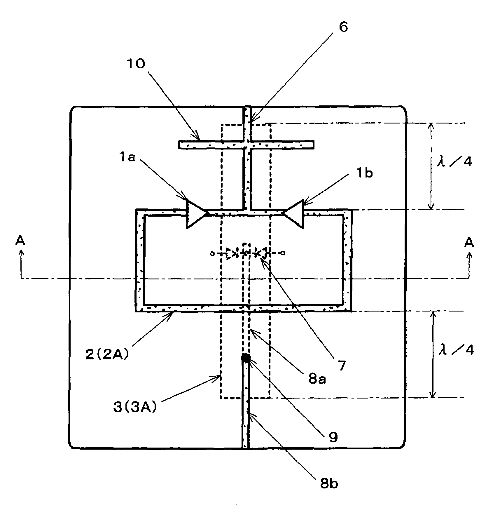
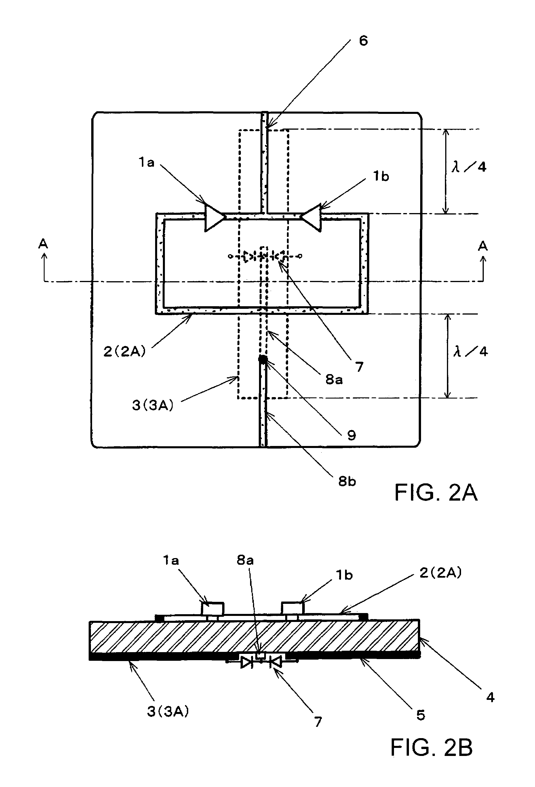
[0026]A planar second-harmonic high frequency oscillator according to a preferred embodiment of the present invention illustrated in FIGS. 2A and 2B additionally includes an electronic device for controlling a wave electromagnetic field of the slot line in accordance with a control signal in the oscillator illustrated in FIGS. 1A and 1B. In FIGS. 2A and 2B, components identical to those in FIGS. 1A and 1B are designated the same reference numerals, and repeated description thereon is simplified.

[0027]The planar second-harmonic oscillator illustrated in FIGS. 2A and 2B, like the one illustrated in FIGS. 1A and 1B, comprises a pair of amplifiers 1a, 1b for oscillation; micro-strip line 2 having output line 6 as a high frequency transmission line; slot line 3 for providing opposite-phase oscillations; and dielectric substrate 4. Electronic device 7 for controlling the electromagnetic wave field of slot line 3 is disposed in a central region of slot line 3 routed on the other principal ...


PUM


Abstract

A planar harmonic high frequency oscillator comprises a pair of amplifiers for oscillation, a micro-strip line for connecting between inputs of the pair of amplifiers and between outputs of the amplifiers, a slot line disposed between the inputs and the outputs of the pair of the amplifiers for electromagnetically coupling with the micro-strip line, an output line connected to the micro-strip line at a position at which the micro-strip line traverses the slot line between the inputs or outputs of the pair of amplifiers, and an electronic device for connecting conductors on both sides of the slot line, and for controlling an electromagnetic wave field of the slot line in response to a control signal applied thereto. Two oscillation systems which oscillate in opposite phases with respect to the fundamental wave of oscillation are formed to generate an even-order harmonic of the fundamental wave.

Description

BACKGROUND OF THE INVENTION[0001]1. Field of the Invention[0002]The present invention relates to a planar higher-harmonic high frequency oscillator for generating even-order harmonics of the fundamental wave such as a second harmonic, a fourth harmonic and the like through so-called push-push oscillation, and more particularly, to a multi-functional planar harmonic high frequency oscillator.[0003]2. Description of the Related Art[0004]An oscillator based on push-push oscillation is known as suitable for generating oscillation signals in a millimeter wave band and a microwave band. The oscillator based on push-push oscillation employs a pair of oscillation circuits which operate at the same fundamental frequency but at opposite phases to each other, and combines the outputs from these oscillation circuits to cancel out the fundamental wave components and extract even-order harmonic components to the outside. In such push-push oscillators, a planar harmonic oscillator, which has oscil...

Claims


Application Information

Patent Timeline
Patent Type & Authority Patents(United States)
IPC IPC(8): H03B7/12H03B19/18H03B5/18
CPCH03B5/1852
Inventor AIKAWA, MASAYOSHITANAKA, TAKAYUKIASAMURA, FUMIOOITA, TAKEO
Owner NIHON DEMPA KOGYO CO LTD
Why Eureka
Try Eureka