Fuel vapor vent valve and method of attaching same to a tank

a technology of fuel vapor and vent valve, which is applied in the direction of machines/engines, manufacturing tools, applications, etc., can solve the problems of inability to properly or accurately position the vent hose connector, the valving surface is destroyed, and the cost of mass production is relatively high

Inactive Publication Date: 2006-12-12
EATON CORP
View PDF26 Cites 8 Cited by
  • Summary
  • Abstract
  • Description
  • Claims
  • Application Information

AI Technical Summary

Benefits of technology

[0003]The present invention provides a float operated vapor vent valve for a fuel tank which may be assembled through an access opening formed in the upper wall of the tank with the float operated valve extending interiorly of the tank and a vent port connection extending exteriorly of the tank. The valve has a flange formed of material compatible for welding to the outer surface of the tank to effect a permanent sealing attachment thereon. The float is slidably movable in the float chamber and has surfaces thereon engaging the wall of the float chamber to prevent relative rotation of the float valve member with respect to the valve body. The slidable rotary float constraint enables spin welding of the flange to the tank without loss of calibration or damage to the valve components. An optional gravity operated pressure relief valve may be incorporated in the vent passage; and, the relief valve also has surfaces thereon slidably engaging the wall of the vent passage to prevent relative rotation of the relief valve poppet during spin welding.

Problems solved by technology

Heretofore the weldment has been by hot-plate or sonic welding techniques which have proven relatively costly in mass production.
Heretofore, attempts to spin weld a fuel vapor vent valve of the present type have resulted in destruction of the valving surfaces by the extreme rotational accelerations and decelerations.
Furthermore, proper or accurate orientation of the vent hose connector was not possible with spin welding.

Method used


Image

  • Fuel vapor vent valve and method of attaching same to a tank
  • Fuel vapor vent valve and method of attaching same to a tank
  • Fuel vapor vent valve and method of attaching same to a tank

Examples


Embodiment Construction

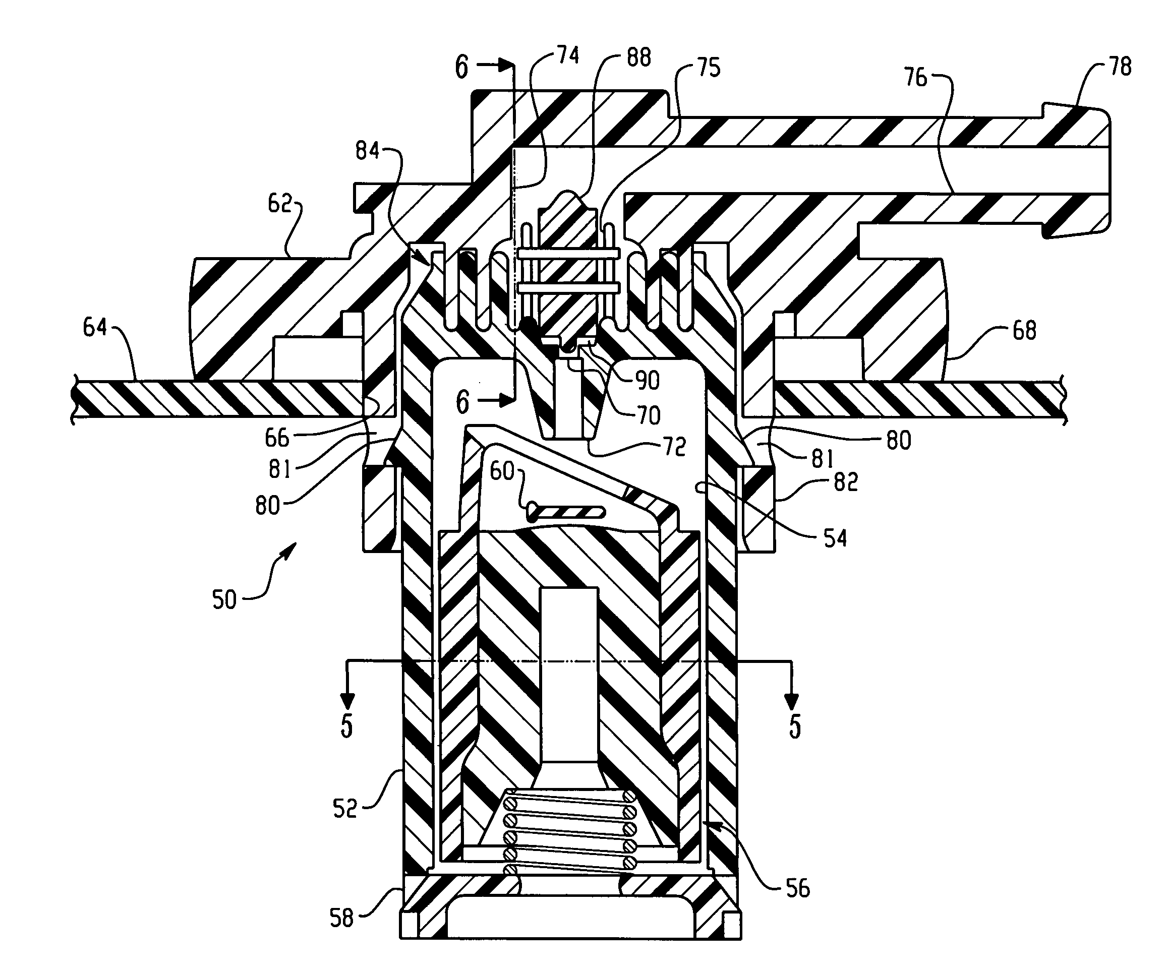
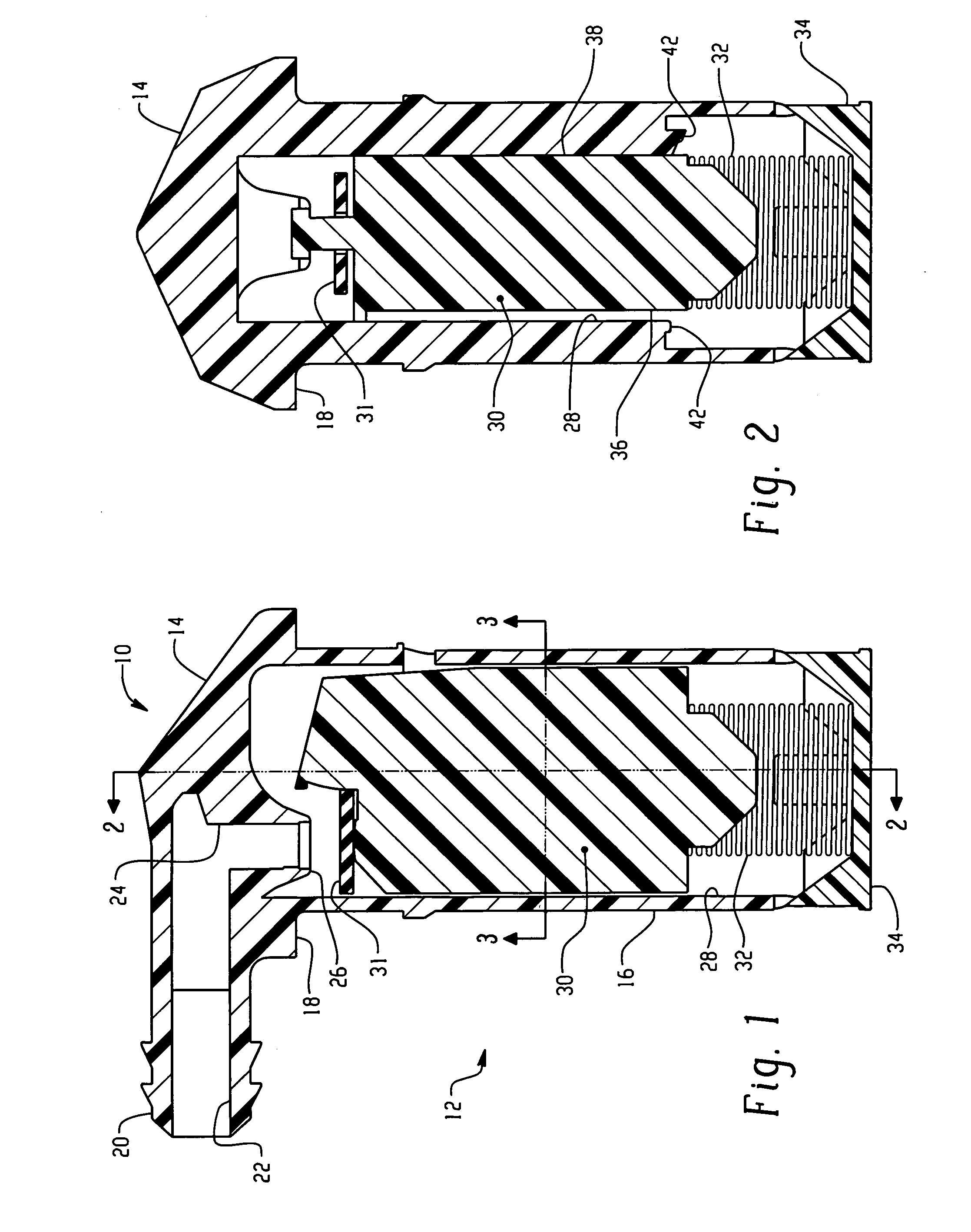
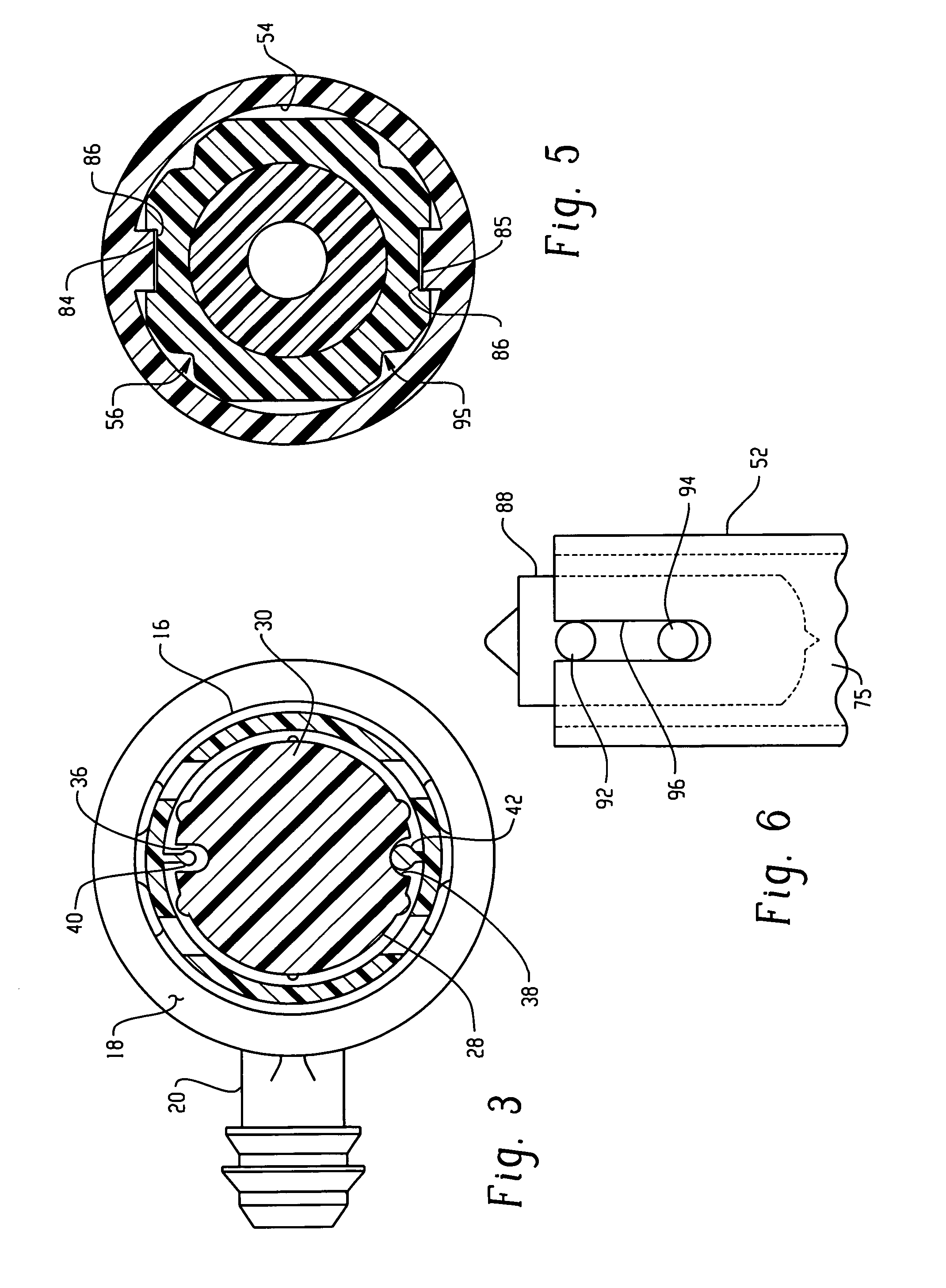
[0010]Referring to FIG. 1, a valve assembly indicated generally at 10 has a unitary or one piece body indicated generally at 12, formed with an upper or exterior portion 14 with an annular mounting flange 18 and a lower portion 16 intended for extending interiorly of the tank. The upper portion has a fitting 20 provided thereon with a vent passage 22 formed therein; and, fitting 20 is adapted for having a flexible hose received thereon for connection thereto. Passage 22 communicates with a downwardly extending passage 24 which has a valve seat 26 formed at the lower end thereof.

[0011]The lower portion 16 of the body has a float chamber 28 formed therein into which is received a float member 30 with a resiliently flexible valve member in the form of a pivoted flapper pad or disk 31 disposed on the upper end of the float 30 for movement therewith.

[0012]The float 30 is biased upwardly by a spring 32 with one end registered against the lower end of the float 30 and the opposite end of t...


PUM

PropertyMeasurementUnit
non-weldableaaaaaaaaaa
weldableaaaaaaaaaa
rotational accelerationsaaaaaaaaaa

Abstract

A float operated fuel vapor vent valve has body structure with an annular mounting flange formed of material weldable to a fuel tank and the flange is spin welded to the tank. The float has surfaces thereon which slidably engage corresponding surfaces in the float chamber to prevent relative rotation of the float with respect to the valve body during spin welding. An optional pressure relief valve in the vent outlet also has surfaces slidably engaging the vent passage to prevent relative rotation during spin welding.

Description

BACKGROUND OF THE INVENTION[0001]The present invention relates to fuel vapor vent valves employed in vapor emission controls systems in motor vehicle fuel tank installations. The invention particularly relates to float operated vent valves attached to the upper wall of a non-metallic fuel tank. Valves employed for such applications are commonly mounted onto the tank through an access opening formed in the upper wall with portions of the valve extending outwardly over the opening and attached to the outer surface of the tank in a sealing arrangement, as for example, by weldment of compatible non-metallic material to the surface of the tank.[0002]Heretofore the weldment has been by hot-plate or sonic welding techniques which have proven relatively costly in mass production. Heretofore, attempts to spin weld a fuel vapor vent valve of the present type have resulted in destruction of the valving surfaces by the extreme rotational accelerations and decelerations. Furthermore, proper or a...

Claims


Application Information

Patent Timeline
Patent Type & Authority Patents(United States)
IPC IPC(8): B21K1/20F16K24/00B29C65/06F02M37/00F02M25/08F16K24/04
CPCF16K24/044Y10T29/49904Y10T29/49412Y10T29/494Y10T29/49426Y10T29/4984Y10T29/49416Y10T137/3099Y10T137/731F02M25/08
Inventor SPINK, KENNETH M.BERGSMA, LEGAL REPRESENTATIVE, ROSEMARYBERGSMA, DECEASED, RUDOLPH
Owner EATON CORP
Why Eureka
Try Eureka