Valve for a hydraulic drive apparatus
- Summary
- Abstract
- Description
- Claims
- Application Information
AI Technical Summary
Benefits of technology
Problems solved by technology
Method used
Image

Examples
Example
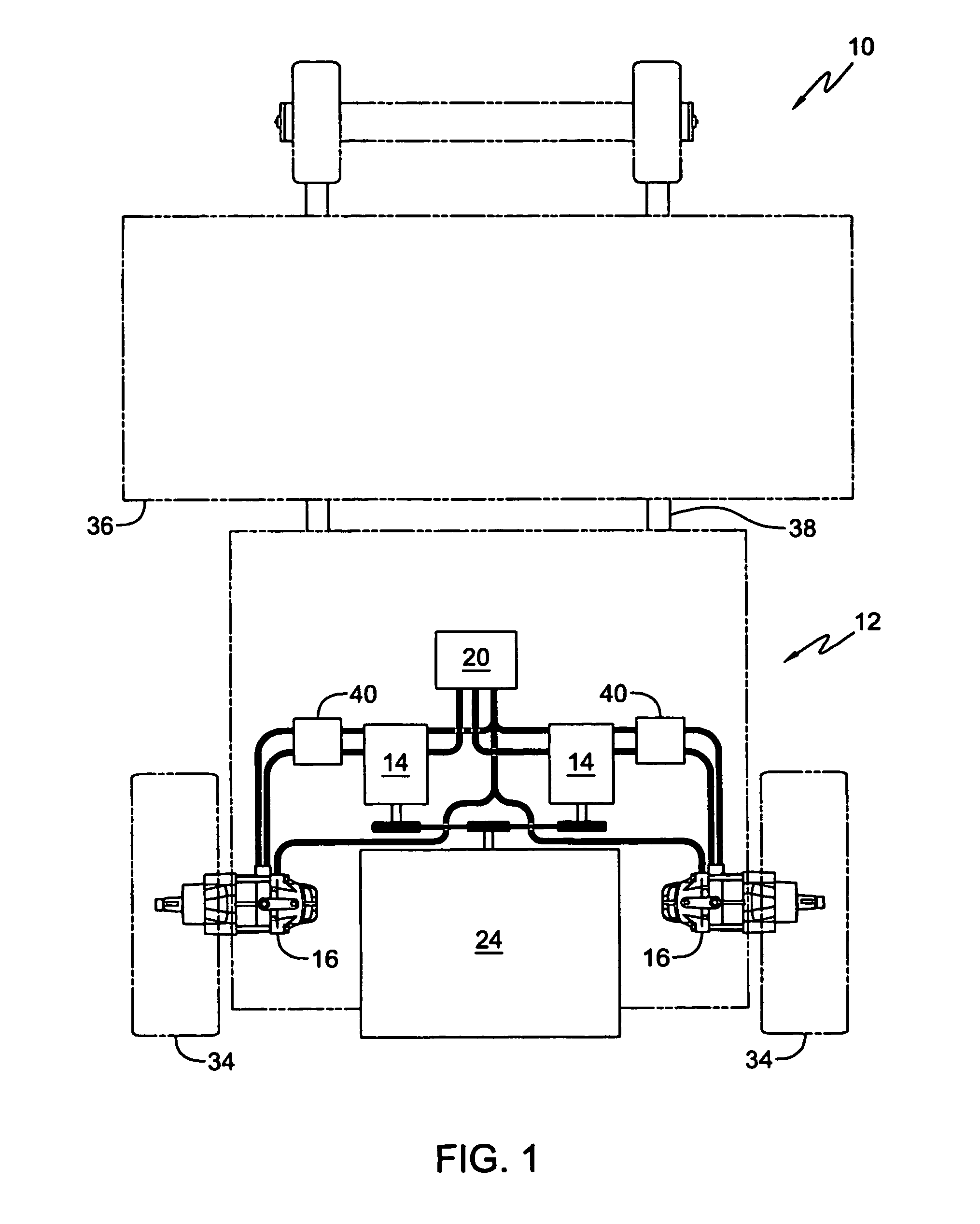
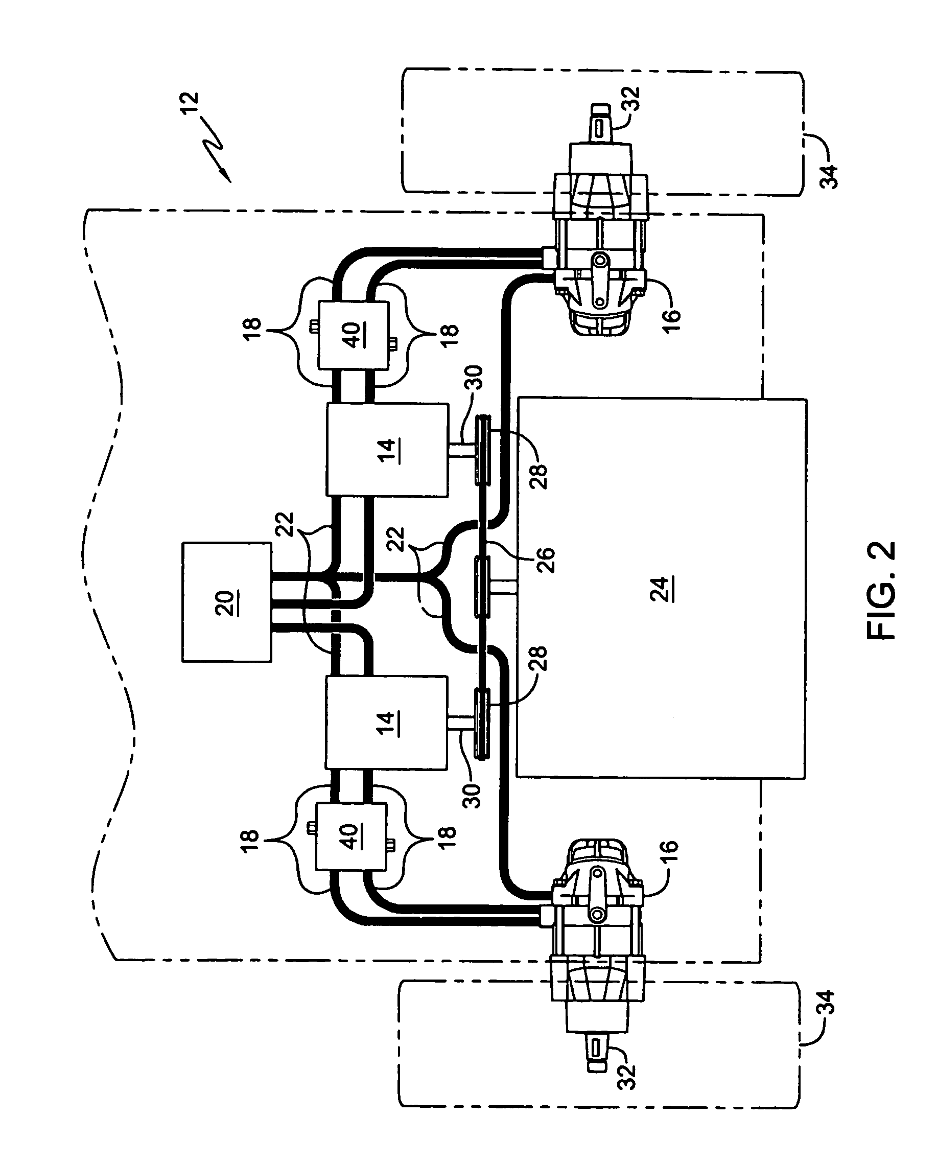
[0031]A second embodiment of this invention is shown in FIGS. 7–10; in this embodiment certain features are identical to those previously described herein and are given identical numerals. As shown in FIG. 7, hydraulic drive system 112 includes valve blocks 140 which are not in line between pump 14 and motor 16 but rather are offset and are connected to the main lines 118 through tee fittings 21. This configuration allows for a less complex design for valve block 140, resulting in less machining required and consequently lower cost. Allowing valve block 140 to be offset from pump 14 and motor 16 enables the user to mount valve block 140 in a wide range of locations in vehicle 110.
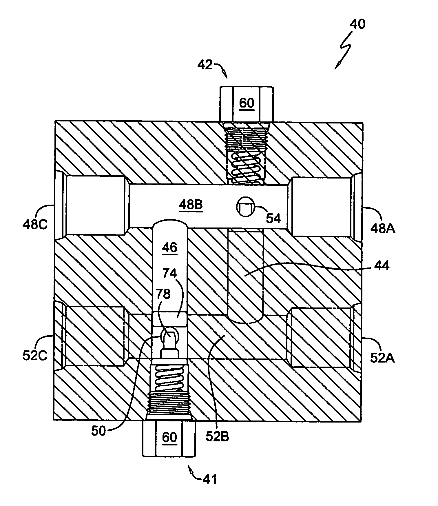
[0032]A cross-sectional view of block 140 is shown in FIG. 10. Valves 141 and 142 can be identical in construction to valves 41 and 42 discussed previously. Block 140 comprises two inlets 86 and 87 connected to separate ports 91 and 93, respectively. A single outlet 88 is connected to an outlet port 85 whic...
PUM
 Abstract
Description
Claims
Application Information
 - R&D Engineer
- R&D Manager
- IP Professional
- Industry Leading Data Capabilities
- Powerful AI technology
- Patent DNA Extraction
Browse by: Latest US Patents, China's latest patents, Technical Efficacy Thesaurus, Application Domain, Technology Topic.
© 2024 PatSnap. All rights reserved.Legal|Privacy policy|Modern Slavery Act Transparency Statement|Sitemap