Counter weight

a counterweight and weight technology, applied in the field of counterweights, can solve the problems of increasing the manufacturing cost of counterweights, reducing the cutting yield of slab materials, and complicated welding of respective heavy-weight objects, so as to improve the attaching precision and reduce the manufacturing cost. , the effect of high precision

Inactive Publication Date: 2006-12-12
KOMATSU LTD
View PDF4 Cites 6 Cited by
  • Summary
  • Abstract
  • Description
  • Claims
  • Application Information

AI Technical Summary

Benefits of technology

[0016]The present invention has been made taking the foregoing problems into consideration and an object of which is to provide a counter weight capable of forming an attaching part to a vehicle frame with high precision, capable of improving attaching precision to this vehicle frame, and further, capable of decreasing a manufacture cost thereof.
[0018]In the above-described counter weight according to claim 1, since the base 1 made of cast iron is attached to the vehicle frame, it is possible to form the attaching part to the vehicle frame at a low cost, simply, and with high precession differently from the conventional case that the counter weight is made of the slab material by cutting. Thereby, misalignment and a slope or the like are hardly generated in the external design of the built counter weight. In addition, since only a part attached to the vehicle frame as the heavy-weight object is made of cast iron and the other part is mainly made of the slab material, it is possible to achieve low cost entirely.
[0020]In the above-described counter weight according to claim 2, since the outer surface of the slab material made weight part 2 is coated with the cover 30, quality of the external design can be improved. In addition, the block body of the slab material made weight part 2 does not expose outside by coating the outer surface thereof with the cover 30. Therefore, precision in cutting the block body is not required so much, and this leads to the fact that cutting machine and assembly work become easy.
[0022]In the counter weight according to claim 3, the lower end edge of the cover 30 is joined to the base 1 made of cast iron via the above-described connecting plate 7, so that it is possible to join this cover 30 and the base 1 made of cast iron certainly. In other words, although welding of the cast iron is generally difficult, it is possible to join this cover 30 and the base 1 made of cast iron certainly by welding the cover 30 to the connection plate 7 that is attached to the base 1 made of cast iron. In addition, since the slab material can be easily welded in the case that the upper end edge of the cover 30 is joined to the upper part of the above-described weight part 2, it is possible to join the weight part 2 made of the slab material to the cover 30 easily. Thus, it is possible to certainly join the cover 30 coating the outer surface of the weight part 2 made of the slab material to the base 1 even when the base 1 is made of cast iron, and this results in stable fitting of the cover 30.
[0024]The above-described counter weight according to claim 4 may cut the slab material in the event of forming the weight part 2 made of the slab material, and it is difficult to finish the outer surface thereof with high precision. Therefore, by bending the plate member 26 made of a copper sheet or the like, the outer surface of the weight part 2 made of the slab material is composed of this plate member 26. Thereby, it is possible to form the outer surface of the weight part 2 made of the slab material into a shape corresponding to the cover 30 with high precision. As a result, the plate member 26 is arranged in the inside of the cover 30, and this makes it possible to decrease modification of the cover 30 even if a large load is given to the cover 30 from the outside and strength of the cover 30 is improved. In addition, since the weight of the plate member 26 is added to the weight of the counter weight, the stable work becomes possible. Further, it is possible to acquire an advantage such that the cover 30 can be easily fit.

Problems solved by technology

In other words, it is necessary to form respective heavy-weight objects 61 into intricate shapes in accordance with the shape of the chassis 60, and this makes it difficult to manufacture the counter weight and makes the manufacturing cost thereof higher.
However, since this heavy-weight object is configured by a slab material, it is necessary to machine this slab material by cutting and it is difficult to cut the slab material into the shape in accordance with the counter weight attaching part with a high precision.
In other words, if the heavy-weight object is configured by the slab material as this counter weight shown in FIG. 10, and that described in the above-described patent document 4, the shape of the heavy-weight object (block) becomes intricate, and this results in decreasing of yield of cutting and in making welding of respective heavy-weight objects complicated.
Therefore, as same as the above-described counter weight shown in FIG. 9, the manufacturing cost of the counter weight becomes high.
Thus, according to the counter weight described in the patent document 2, it is difficult to form the attaching part to the vehicle frame with high precision, and depending on a degree of alignment to the shape of the counter weight attaching part at the vehicle frame side, it is feared that misalignment and a slope or the like are generated in an external design of the built counter weight and a commercial value thereof is lowered.
In addition, according to the counter weight described in the patent document 3, in the upper counter weight and the middle counterweight, a plurality of iron plates is accumulated, respectively, so that its manufacturing cost is high.
Further, this counter weight has the upper and middle counter weights, and this result in complicated manufacture of the counter weight.

Method used


Image

  • Counter weight
  • Counter weight
  • Counter weight

Examples


Embodiment Construction

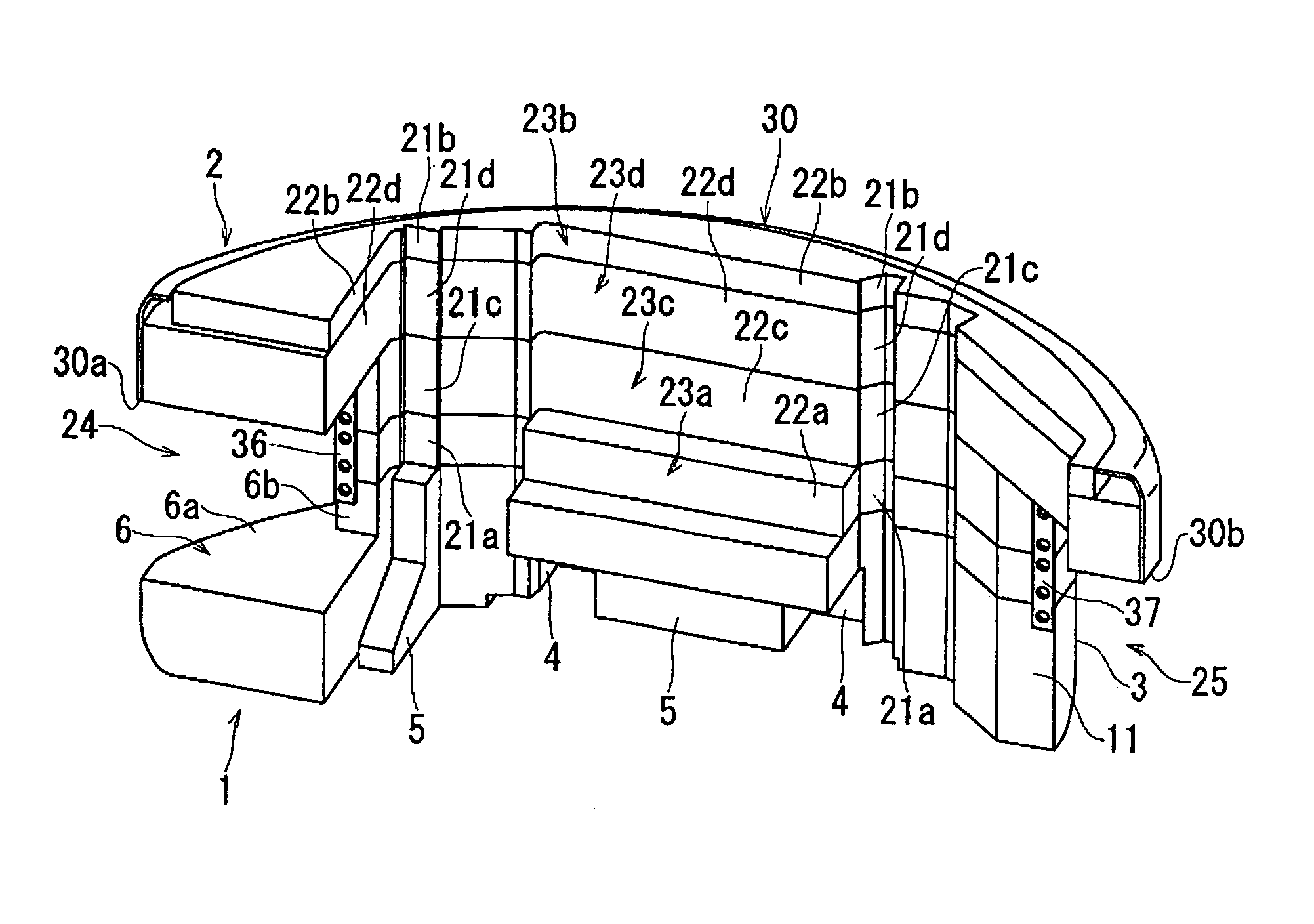
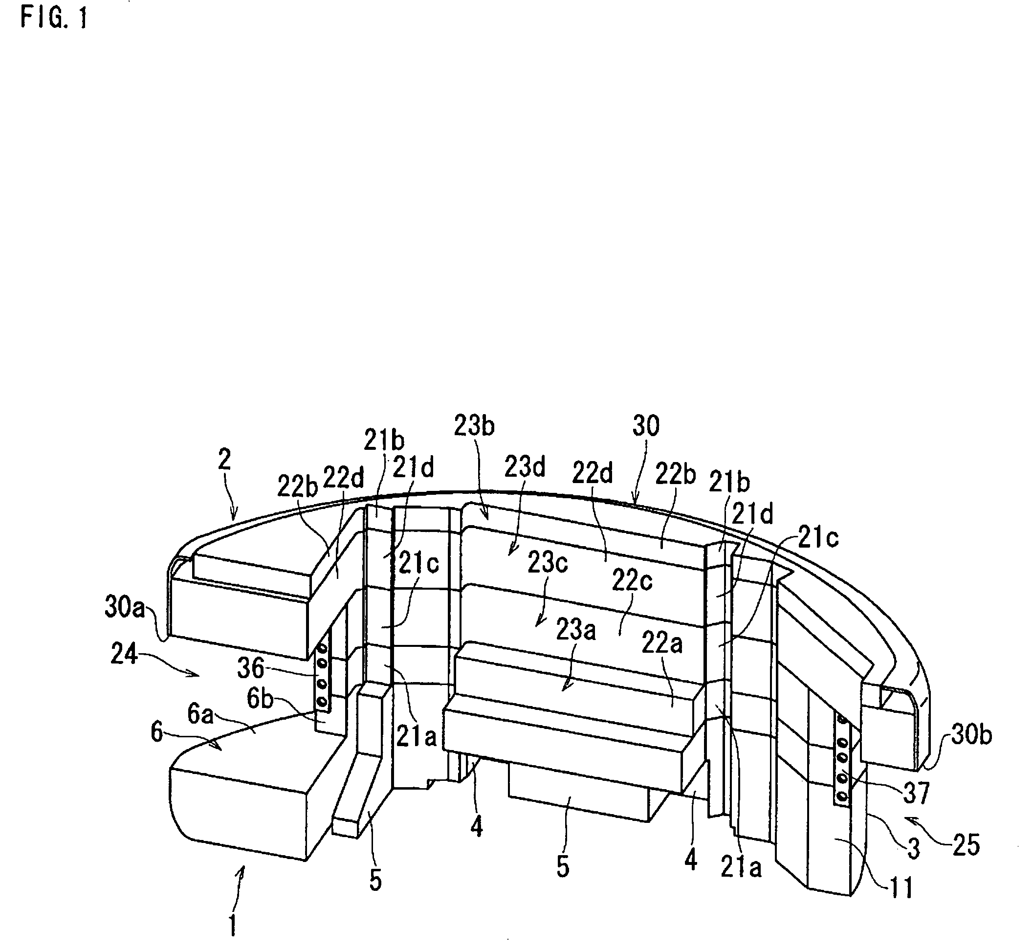
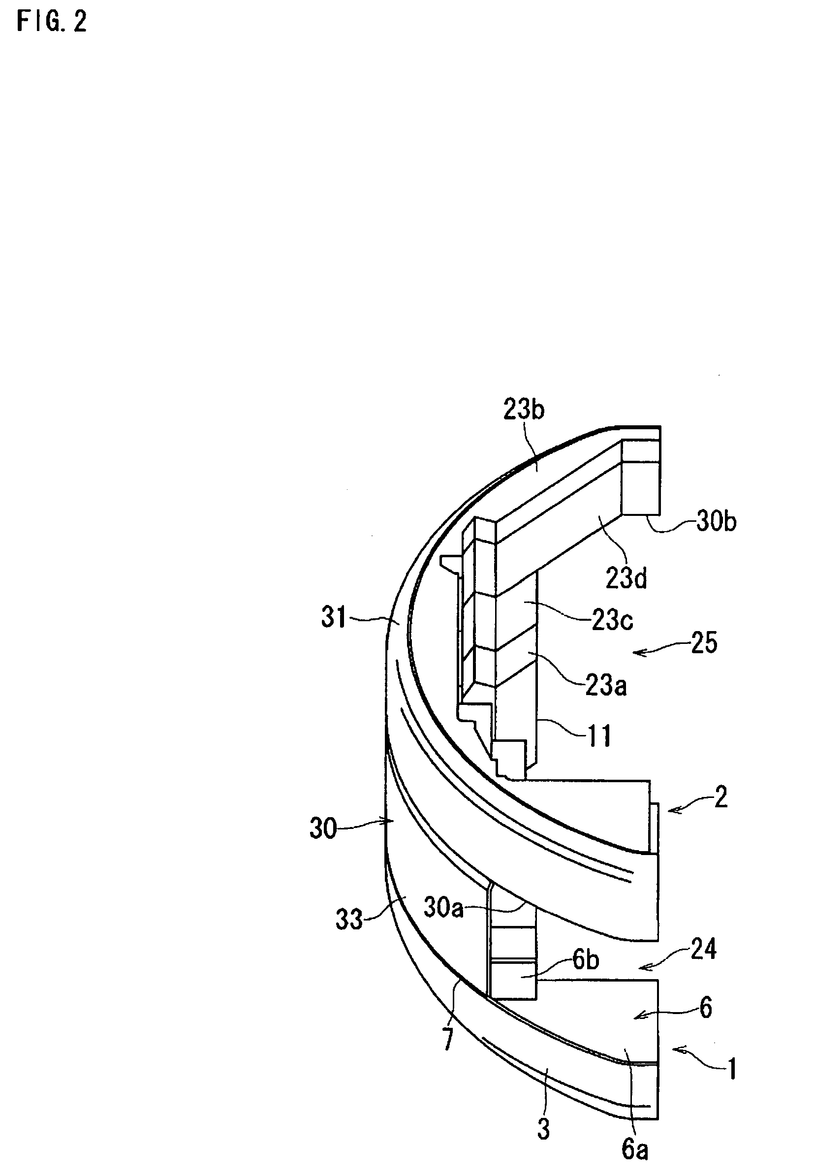
[0036]With reference to the drawings, embodiments according to the counter weight of the present invention will be described in detail below. FIG. 1 is a perspective view seen from the inside of a counter weight, and FIG. 2 is a perspective view seen from the outside of the above-described counter weight. This counter weight have a base 1 made of cast iron and a weight part 2 made of a slab material that is mounted on this base 1 made of cast iron and this counter weight is used for, for example, a construction machine such as a hydraulic shovel or the like.

[0037]As shown in FIGS. 1 to 3, an outer surface 3 of the base 1 made of cast iron is a circle shape, the base 1 made of cast iron is composed of a circle block in which a concave portion 4 and a convex portion 5 are formed, and a crena portion 6 is formed at the upper part of one end side thereof. In addition, for example, this base 1 made of cast iron is provided with a connection plate 7. The connection plate 7 is made of stee...


PUM


Abstract

To provide a counter weight capable of forming an attaching part to a vehicle frame with high precision, capable of improving attaching precision to this vehicle frame, and further, capable of decreasing a manufacture cost thereof. The counter weight includes a base made of cast iron having an attaching part, whereby the counter weight is attached to a vehicle frame; and a weight part made of a slab material having a block body made of a slab material; wherein the weight part made of the slab material is attached on the above-described base made of cast iron. The outer surface of the above-described weight part made of the slab material is coated with the cover. In addition, the connection plate is attached to the above-described base made of cast iron, the lower end edge of the above-described cover is joined to the base made of cast iron through the above-described connection plate, and the upper end edge of the above-described cover is joined to the upper part of the above-described weight part made of the slab material. Since the base made of cast iron is attached to the vehicle frame, it is possible to form the attaching part to the vehicle frame at a low cost, simply, and with high precession.

Description

BACKGROUND OF THE INVENTION[0001]1. Field of the Invention[0002]The present invention relates to a counter weight to be used for a construction machine or the like.[0003]2. Description of the Related Art[0004]A construction machine such as a hydraulic shovel or the like is generally used for a counter weight. In other words, as shown in FIG. 8, a hydraulic shovel is provided with a lower traveling body 51, and an upper pivoting body 52 to be pivotably fitted in this lower traveling body 51 via a pivoting mechanism; and a counter weight 53 is arranged at a rear part of this upper pivoting body. In addition, an operating machine 54 is connected to the upper pivoting body 52. This operating machine 54 is provided with a boom 55, of which base is swingably coupled with the upper pivoting body 52; an arm 56 that is swingably coupled with a front end of this boom 55; and a bucket 57 that is swingably coupled with a front end of this arm 56.[0005]Then, as this counter weight 53, a chassis ...

Claims


Application Information

Patent Timeline
Patent Type & Authority Patents(United States)
IPC IPC(8): B60R21/00B62D49/08B66C23/74B66C23/76E02F9/18
CPCB62D49/085B66C23/74E02F9/18B21D43/003
Inventor KUBO, KAZUHIROKAJIYA, MASATOSHIKAWAHASHI, MORIHIKO
Owner KOMATSU LTD
Why Eureka
Try Eureka