
Undersea vehicle

a technology for underwater vehicles and underwater structures, applied in underwater equipment, special-purpose vessels, vessel construction, etc., can solve problems such as unacceptably high unsatisfactory acoustic noise levels of present control surfaces and propulsor configurations,

Inactive Publication Date: 2006-12-12
THE UNITED STATES OF AMERICA AS REPRESENTED BY THE SECRETARY OF THE NAVY
View PDF7 Cites 24 Cited by
  • Summary
  • Abstract
  • Description
  • Claims
  • Application Information

AI Technical Summary

Benefits of technology

[0007]Accordingly, it is an object of the present invention to provide an undersea vehicle having low-emitted noise caused by propulsor-control surface interaction.
[0008]It is a further object of the invention to provide an undersea vehicle having reduced turbulence in the propulsor region.
[0009]It is another object of the invention to provide an undersea vehicle having reduced turbulence in the control surface region.
[0011]It is still another object of the invention to provide a reduced acoustic signature of the propulsor in the forward hemisphere.
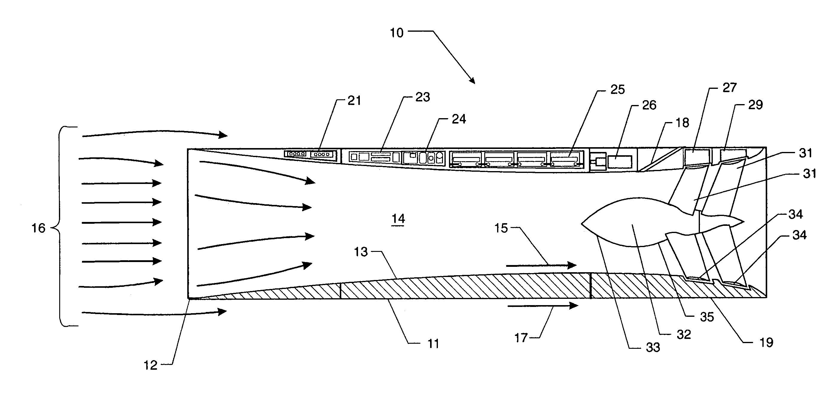
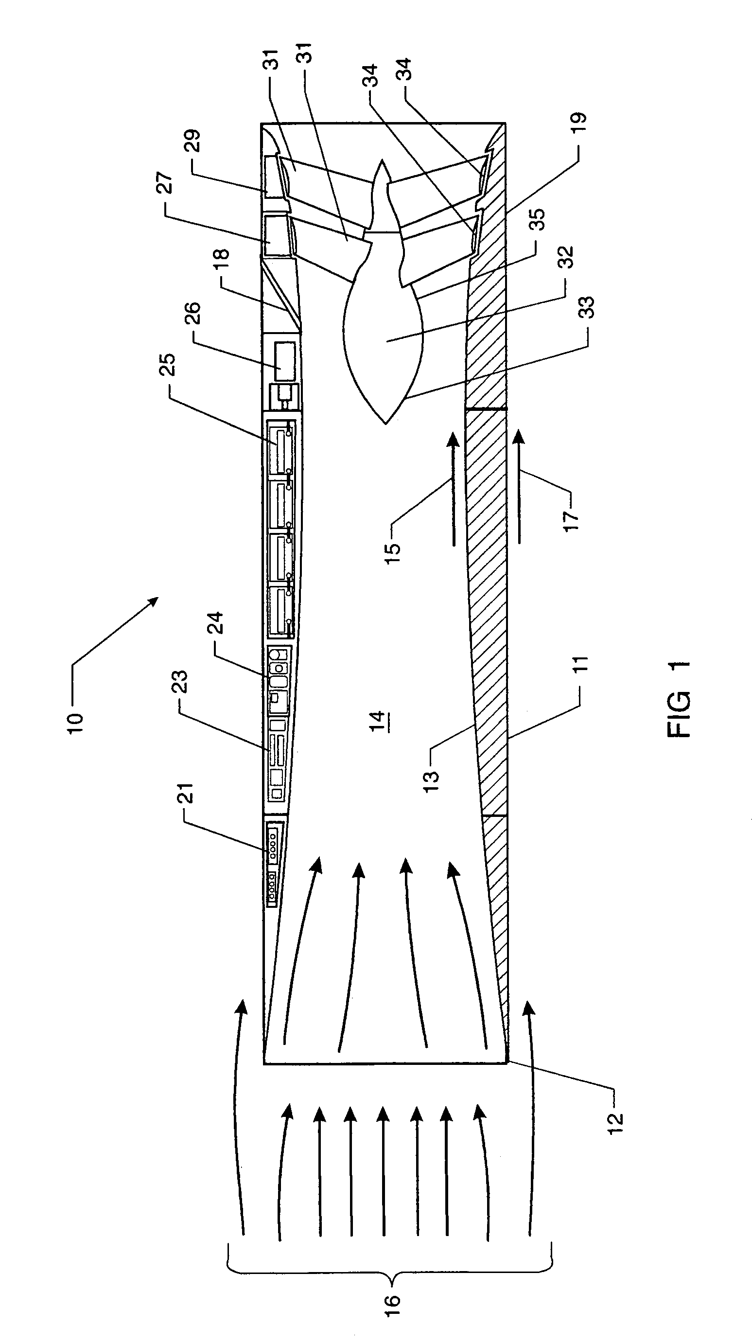
[0012]The foregoing and other objects are realized by providing a hollow undersea vehicle having an internal ducted propulsor system and having internal and external shaping to avoid forward emission of acoustic energy. The external hull is a nearly planar cylinder providing a smooth, low turbulence surface. This surface reduces reflectivity toward the forward hemisphere of any active sonar energy received from the forward hemisphere. Additionally, the internal inlet tube is shaped to trap acoustic energy entering the inlet. The aft portion of the hollow body is shaped to avoid both reflected and emitted noise in the forward direction. The canting of the leading surfaces of the inlet and the trailing surface of the exhaust nozzle provide for maneuver and control, thereby avoiding reflective surfaces and reducing control surface turbulence. The result is a low noise and non-reflective body as viewed from a frontal hemisphere.

Problems solved by technology

It is well known that control surface actuator noise, as well as turbulence induced noise created by the interaction of propellers and control surfaces, are significant sources of unwanted noise on undersea vehicles, such as torpedoes and unmanned undersea vehicles.
Present control surfaces and propulsor configurations have unacceptably high acoustic noise levels.
Unfortunately, even in the best prior art designs, electromechanical actuator-driven control surfaces suffer from several drawbacks.
Actuation of the control surfaces result in gear and motor noise.
Further, these control surfaces, typically located ahead of the propellers, create a turbulent wake behind the control surfaces.
The ingestion of this wake by the propellers generates significant flow noise levels.
The conventional structure of fins, control surfaces and propellers creates multiple corner reflectors resulting in very strong return echoes.

Method used


Image

  • Undersea vehicle
  • Undersea vehicle
  • Undersea vehicle

Examples


Embodiment Construction

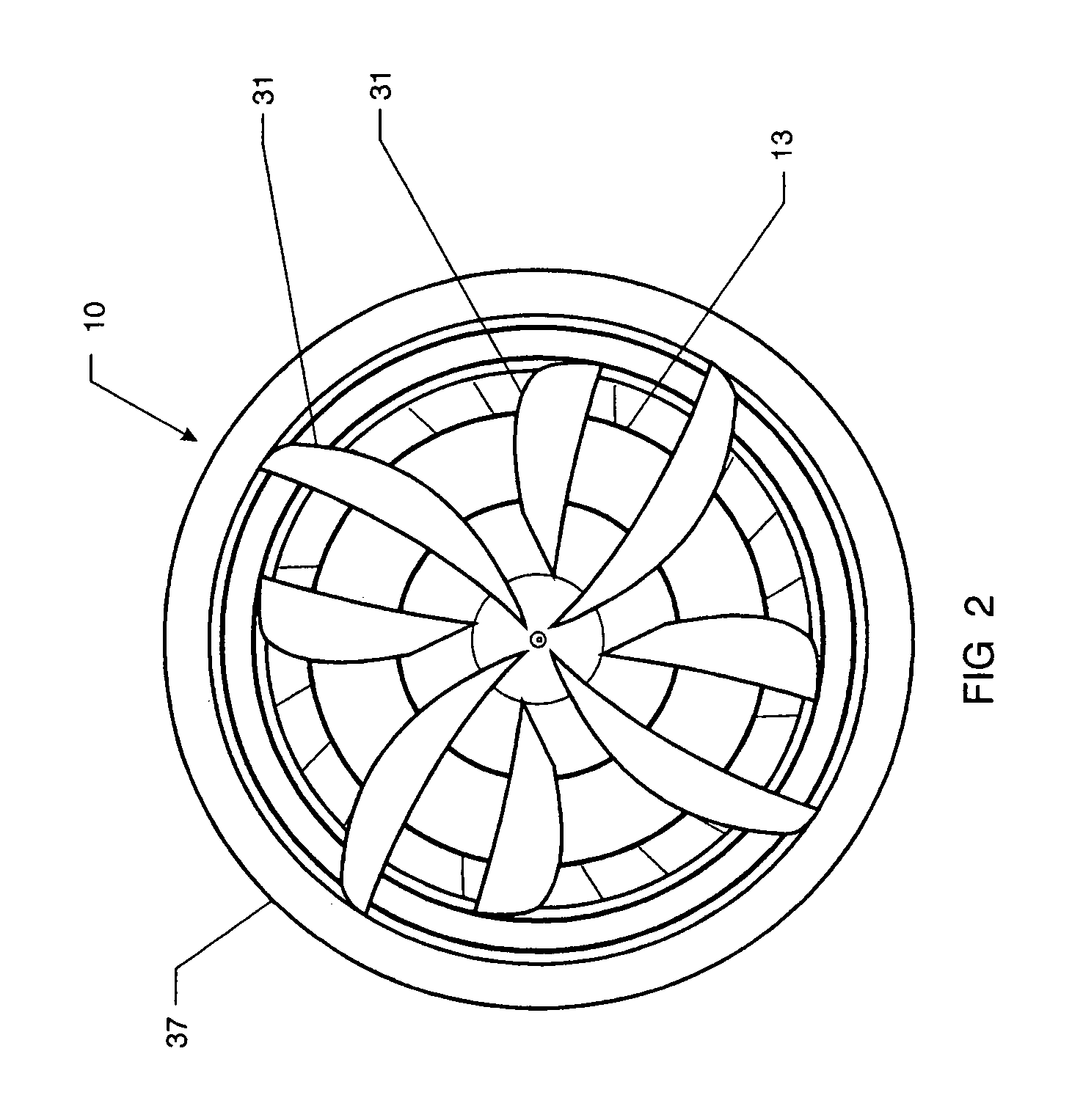
[0017]Referring now to FIG. 1, the undersea vehicle, designated generally by the reference numeral 10, is shown with its major components. The vehicle has a hollow cylindrical hull 11 which encloses an internal duct 14. Hollow cylindrical hull 11 has three sections, an intake section 12, a throat section 13 and an output section 19. Intake section 12 has a sharpened leading edge. The payload and the operating elements of the vehicle are located between the hull 11 and the wall of the internal duct 14. The payload in this embodiment is an array of sensors 21, as used for a surveillance vehicle. Alternatively, a warhead and fusing mechanism can replace the sensor array 21. A central processor unit 23 receives information from the sensor array 21 and generates data to the guidance and control unit 24. A plurality of batteries located in the battery pack 25 provides power to operate the onboard electronics (sensors, navigation, control, and computer processor) and to operate a propulsio...


PUM


Abstract

An undersea vehicle having both low emitted noise and low reflectivity is provided. The undersea vehicle has a hollow cylindrical hull with all components, sensors, electronics, motors, and other internal components with the exception of the propellers, located within the shell of the cylindrical hull. The hollow center of the hull provides a duct and propeller configuration with the shaping of the inlet tube designed to reduce forward noise transmissions, such as reflected active sonar signals and emitted noise. The internal duct gradually constricts to a throat section and thereafter diverges to an output section where dual counter-rotating propellers are located. The result is that most of the internal turbulent flow and the propeller noise is located behind the throat and is thereby reflected in the aft direction. Steering of the vehicle is accomplished by canting the leading edge intake section and the duct exhaust section.

Description

STATEMENT OF GOVERNMENT INTEREST[0001]The invention described herein may be manufactured and used by or for the Government of the United States of America for Governmental purposes without the payment of any royalties thereon or therefor.BACKGROUND OF THE INVENTION[0002](1) Field of the Invention[0003]The present invention relates generally to quiet undersea vehicles and more particularly to undersea vehicles having internal or ducted propulsor systems.[0004](2) Description of the Prior Art[0005]It is well known that control surface actuator noise, as well as turbulence induced noise created by the interaction of propellers and control surfaces, are significant sources of unwanted noise on undersea vehicles, such as torpedoes and unmanned undersea vehicles. Present control surfaces and propulsor configurations have unacceptably high acoustic noise levels. A variety of techniques have been used to reduce the amount of noise created by existing electromechanical actuators. In general,...

Claims


Application Information

Patent Timeline
IPC IPC(8): F42B19/01
CPCB63C11/42B63G8/001B63G8/34B63H5/10B63H5/14F41H3/00
Inventor RICE, JAMES Q.
Owner THE UNITED STATES OF AMERICA AS REPRESENTED BY THE SECRETARY OF THE NAVY
Learn More