Transition between a microstrip circuit and a waveguide including a band stop filter and outside transmission reception unit incorporating the transition

a microstrip circuit and waveguide technology, applied in the field of transition between a microstrip circuit and a waveguide, can solve the problems of interference between transmission and reception, preventing the possibility of an effective bandpass filter for so close a frequency, and high-power transmitted signals will disturb low-power received signals

Active Publication Date: 2006-12-12
INTERDIGITAL MADISON PATENT HLDG
View PDF7 Cites 10 Cited by
  • Summary
  • Abstract
  • Description
  • Claims
  • Application Information

AI Technical Summary

Benefits of technology

[0010]The invention proposes to remedy the problem related to the bandstop filter by introducing one or more cavities at the transition between the microstrip circuit and the waveguide.

Problems solved by technology

A known problem with respect to the transmission standards defined by the public organizations for allocating frequency is that they require that transmitted signals should come within a specific transmission spectrum template.
Another known problem relates to the coupling between transmission and reception.
Specifically, the same antenna being used for transmission and for reception, the high-power transmitted signals will disturb the low-power received signals.
The local oscillator used for transmission may be at a frequency lying very near the transmission band and precludes the possibility of an effective bandpass filter for so close a frequency.
However, such filteing is not sufficient and requires the addition of a bandsrop filter 5 to attenuate the signal corresponding to the frequency of the local oscillator 2 by at least 50 dB.
Microstrip technology does not permit a good quality factor to be obtained in respect of the embodying of the bandstop filter 5.

Method used


Image

  • Transition between a microstrip circuit and a waveguide including a band stop filter and outside transmission reception unit incorporating the transition
  • Transition between a microstrip circuit and a waveguide including a band stop filter and outside transmission reception unit incorporating the transition
  • Transition between a microstrip circuit and a waveguide including a band stop filter and outside transmission reception unit incorporating the transition

Examples


Embodiment Construction

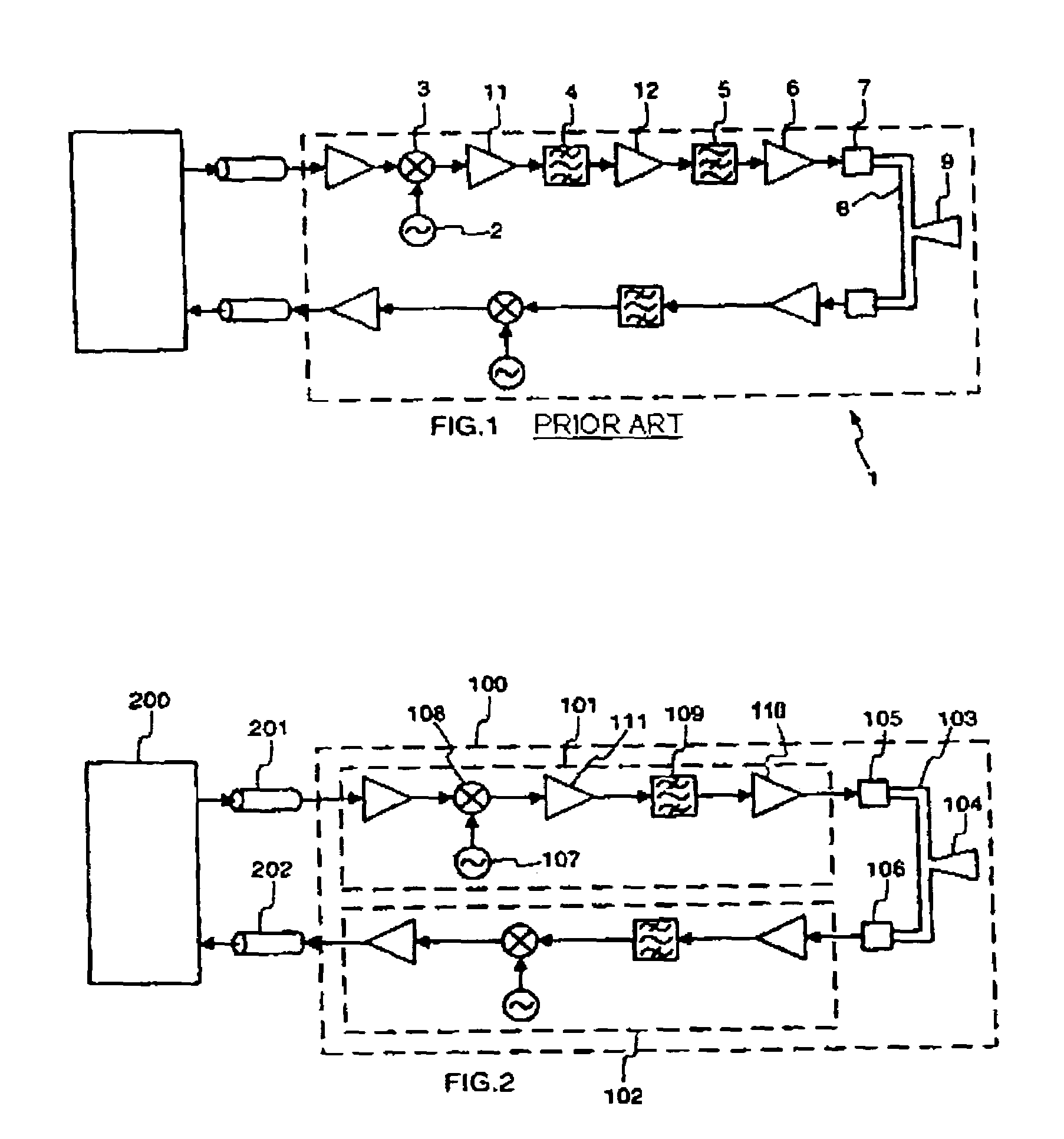
[0021]FIG. 1 having already been described, it will not be detailed further.

[0022]FIG. 2 diagrammatically represents a bidirectional communication system according to the invention. The communication system is for example a satellite communication system that comprises an outside unit 100 linked to an inside unit 200 by way of two coaxial cables 201 and 202.

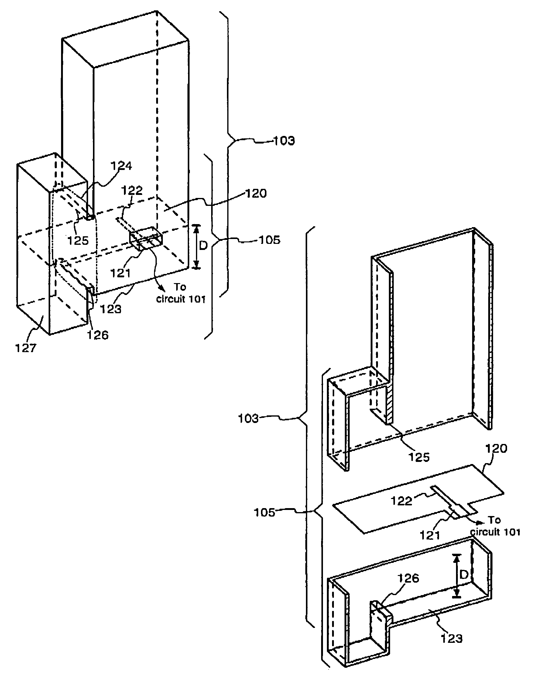
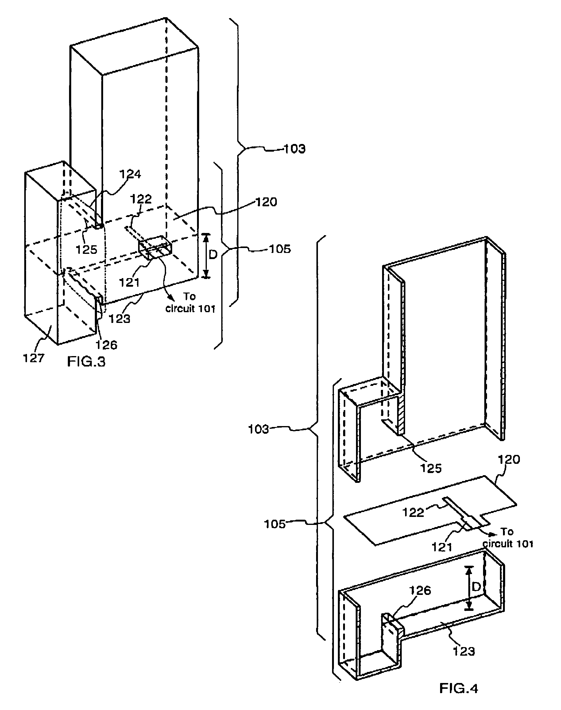
[0023]The outside unit 100 comprises a transmit circuit 101 and a receive circuit 102 embodied in microstrip technology. A waveguide 103 embodies the junction between a horn 104 and, on the one hand, the transmit circuit 101 by way of a transition 105, and on the other hand, the receive circuit 102 by way of a transition 106. Focusing means (not represented), such as for example a parabolic reflector, face the horn so as to direct the waves in a given direction. The transition 105 linking the transmit circuit 101 and the waveguide 103 includes a bandstop filter and will be detailed in greater detail with the aid of FIGS. 3 to 6.

[...


PUM


Abstract

The invention proposes a transition between a microstrip technology circuit and a waveguide, the waveguide being furnished with a probe linked electrically to the microstrip circuit. The transition comprises at least one first resonant cavity coupled by a first hole placed level with the said plane. The transition furnished with the cavity behaves as a bandstop filter. The transition is placed in an outside unit of a transmission system comprising a transmit circuit embodied in microstrip technology and an antenna of waveguide type. A transmit circuit comprises at least one local oscillator and the resonant cavity is tuned to the frequency of the local oscillator.

Description

[0001]This application claims the benefit under 35 U.S.C. § 119(a) of French patent application No. 0301429 filed Jan. 31, 2003.BACKGROUND OF THE INVENTION[0002]1. Field of the Invention[0003]The invention pertains to a transition between a microstrip circuit and a waveguide. More particularly, the transition which is the subject of the invention corresponds to a transition for a transmit circuit of an outside transmit / receive unit. The invention pertains also to the outside transmit / receive unit.[0004]2. Related Art[0005]Bidirectional-satellite transmissions are being called on to develop, within the mass marker sector, low-cost solutions are currently being sought so as to be able to disseminate them on a large scale. For a bidirectional system, it is preferable to use one antenna rather than two antennas.[0006]A known problem with respect to the transmission standards defined by the public organizations for allocating frequency is that they require that transmitted signals should...

Claims


Application Information

Patent Timeline
Patent Type & Authority Patents(United States)
IPC IPC(8): H01P5/107H01P1/209H04B1/48
CPCH01P1/209H01P5/107
Inventor TONG, DOMINIQUE LO HINEPINTOS, JEAN-FRANCOISMINARD, PHILIPPE
Owner INTERDIGITAL MADISON PATENT HLDG
Why Eureka
Try Eureka