Optical device having a plurality of optical modulator units, projector equipping the same, and particular heat insulation
a technology of optical modulator and optical device, which is applied in the direction of projectors, color television details, instruments, etc., to achieve the effects of suppressing deterioration, enhancing brightness, and reducing cooling fan nois
- Summary
- Abstract
- Description
- Claims
- Application Information
AI Technical Summary
Benefits of technology
Problems solved by technology
Method used
Image

Examples
first exemplary embodiment
1. First Exemplary Embodiment
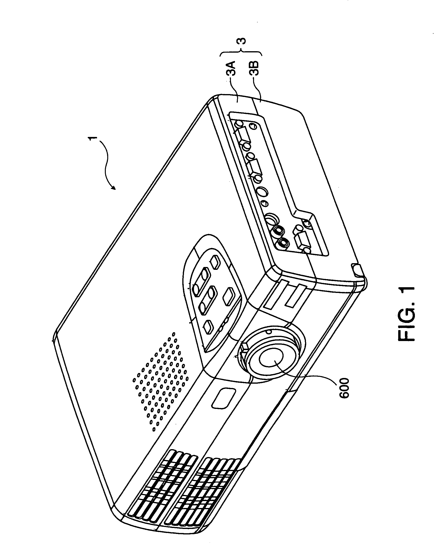
[0061]Hereunder, explanations will be made on an optical device and a projector having the same, based on the exemplary embodiments shown in the drawings. In the outset, the first exemplary embodiment of the invention will be explained by using FIGS. 1 through 7.
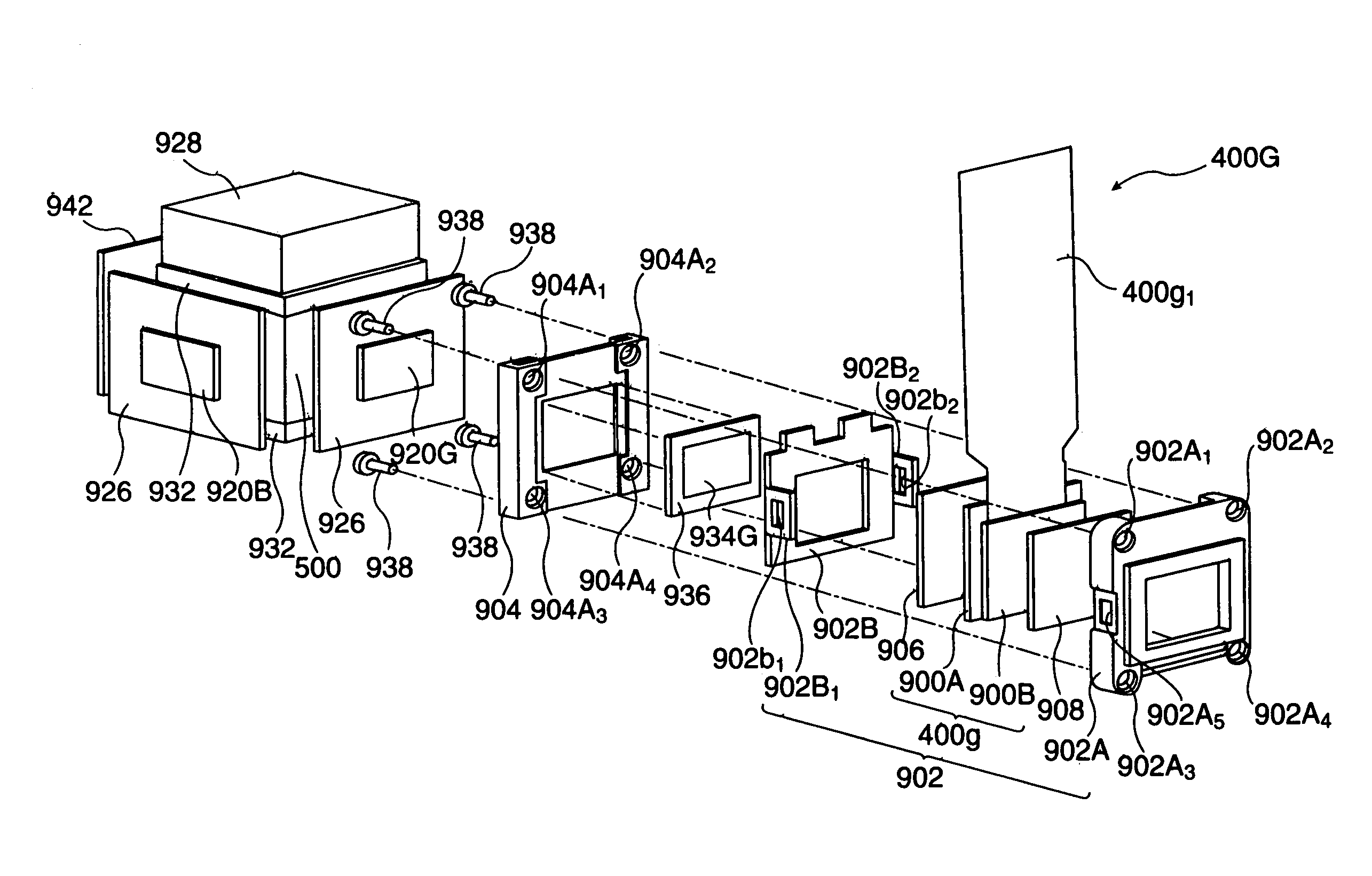
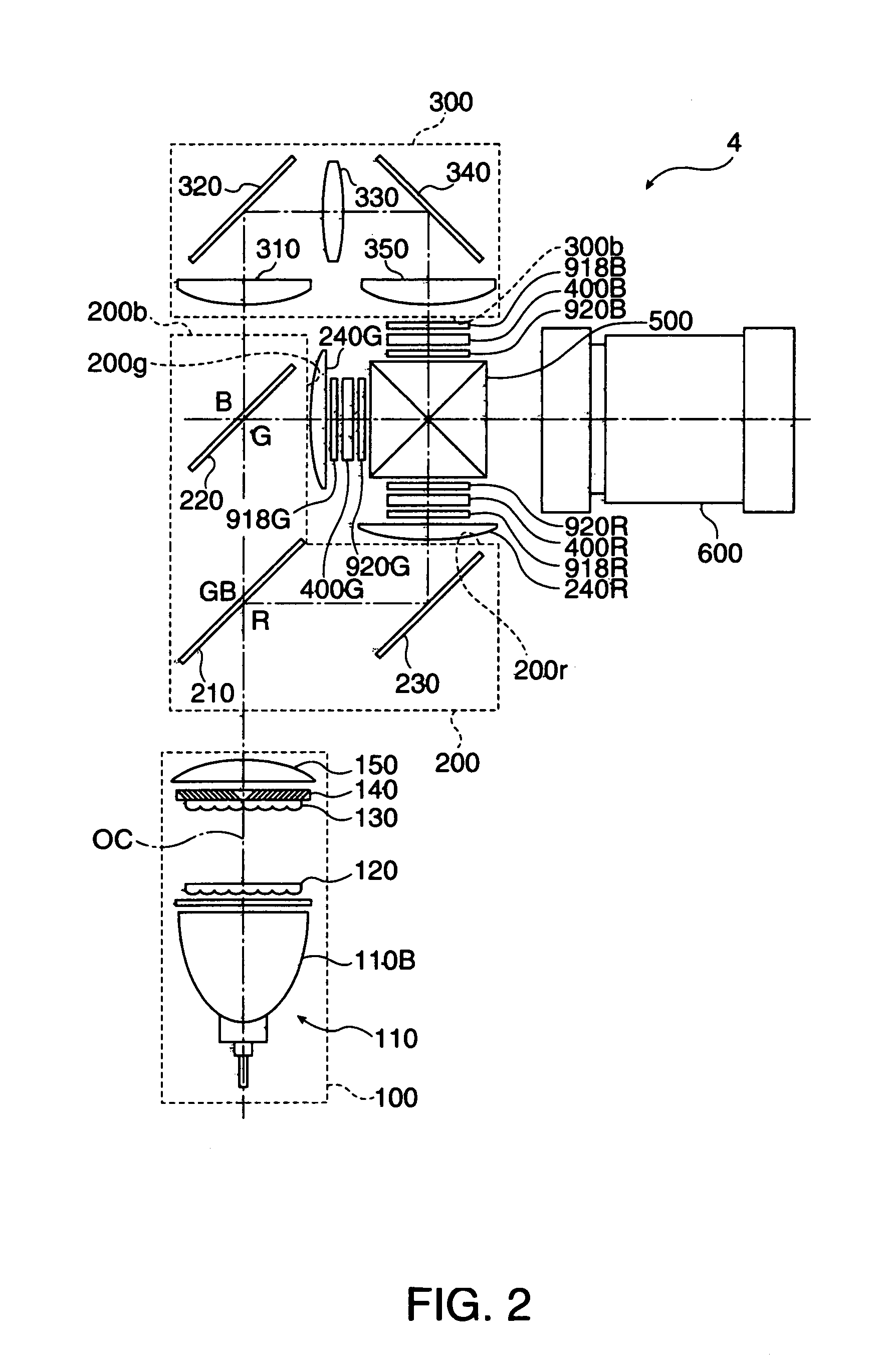
[0062]FIG. 1 is a schematic showing an exterior appearance of a projector provided with an optical modulator unit according to the first exemplary embodiment of the invention. FIG. 2 is a schematic showing a schematic structure of an optical system in the projector of FIG. 1. FIG. 3 is a schematic showing an exploded state of mounting, onto a color-combining optical unit, a liquid-crystal display according to the first exemplary embodiment of the invention. FIG. 4 is a schematic showing an arrangement, within an optical part housing, of a liquid-crystal display and color-combining optical unit according to the first exemplary embodiment of the invention. FIGS. 5(a) and 5(b) are respectively, a sc...
second exemplary embodiment
2. Second Exemplary Embodiment
[0107]Next, a second exemplary embodiment of the invention is explained with using FIG. 8.
[0108]FIG. 8 is a schematic showing an optical device according to a second exemplary embodiment of the invention. In FIG. 8, the members that are the same as FIG. 3 are attached with the same references, omitting the detailed explanations.
[0109]The optical device shown in this exemplary embodiment is characterized in that the first exit polarizer plate and the second exit polarizer plate are joined with each other, allowing for heat conduction.
[0110]For this reason, on a first heat conductor plate 926 arranged at a G-light incident side of the color-combining optical system 500, a second heat conductor plate 936 to be bonded with a second exit polarizer plate 934G is adhered allowing for heat conduction through a metal frame 904 as a polarizer-plate holding frame.
[0111]Likewise, on a first heat conductor plate 926 arranged at a R•B-light incident side of the color...
third exemplary embodiment
3. Third Exemplary Embodiment
[0120]Although the above exemplary embodiment had the exit polarizer plates on all the optical paths for red, green and blue made by two exit polarizer plates (first and second exit polarizer plates), the invention is not limited to this. For example, the exit polarizer plate on the green optical path may be made by two exit polarizer plates (first and second exit polarizer plates) or the exit polarizer plate on the green and blue optical path may be made by two exit polarizer plates (first and second exit polarizer plates).
[0121]Because this also allows the heat, as generated in one exit polarizer plate on the green or green-and-blue optical path, to generate separately on the two exit polarizer plates, it is possible to suppress the temperature rise on the exit polarizer plates in a position where the problem of temperature rise is conventionally conspicuous, and to suppress deterioration.
PUM
| Property | Measurement | Unit |
|---|---|---|
| heat conductive | aaaaa | aaaaa |
| heat conductivity | aaaaa | aaaaa |
| temperature | aaaaa | aaaaa |
Abstract
Description
Claims
Application Information
 - R&D
- Intellectual Property
- Life Sciences
- Materials
- Tech Scout
- Unparalleled Data Quality
- Higher Quality Content
- 60% Fewer Hallucinations
Browse by: Latest US Patents, China's latest patents, Technical Efficacy Thesaurus, Application Domain, Technology Topic, Popular Technical Reports.
© 2025 PatSnap. All rights reserved.Legal|Privacy policy|Modern Slavery Act Transparency Statement|Sitemap|About US| Contact US: help@patsnap.com