
Resonant element transducer

a resonant element and transducer technology, applied in the direction of resonant transducers, transducer diaphragms, electromechanical transducers, etc., can solve the problems of loss of available efficiency, difficulty in matching to an acoustic radiator, especially to the air, etc., to reduce the high amplitude resonance of the resonant element, enhance the distribution of modes, and smooth peak

Inactive Publication Date: 2006-12-12
GOOGLE LLC
View PDF53 Cites 44 Cited by
  • Summary
  • Abstract
  • Description
  • Claims
  • Application Information

AI Technical Summary

Benefits of technology

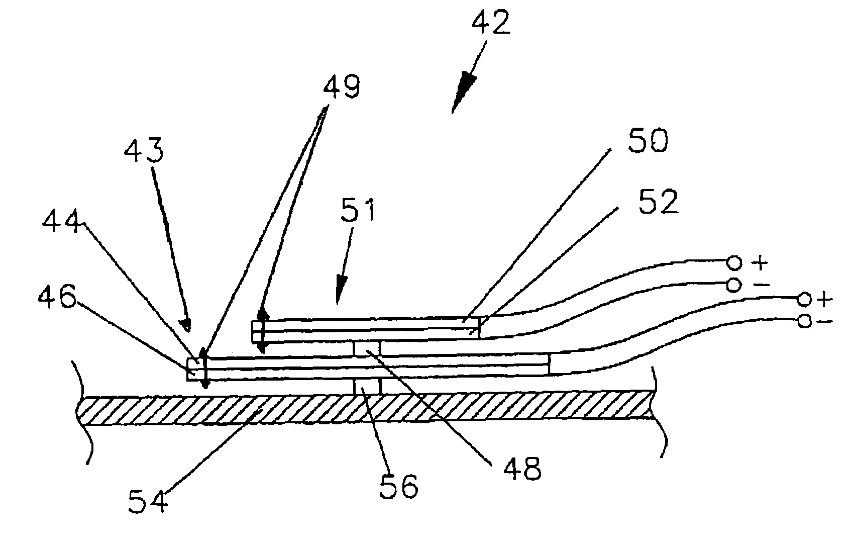
[0015]The resonant element may be passive and may be coupled by a connector to an active transducer element which may be a moving coil, a moving magnet, a piezoelectric, a magnetostrictive or an electret device. The connector may be attached to the resonant element at a position which is beneficial for enhancing modal activity in the resonant element. The passive resonant element may act as a near low loss, resistive mechanical load to the active element and may improve power transfer and mechanical matching of the active element to a diaphragm to which force is to be applied. Thus, in principle the passive resonant element may act as a short term resonant store. The passive resonant element may have low natural resonant frequencies so that its modal behaviour is satisfactorily dense in the range where it performs its loading and matching action for the active element. One effect of the designed close coupling of an active element to such a resonant member is to blend the force produced by the transducer more evenly over the frequency range. This is achieved by cross coupling and control of extreme Q values and the result is a smoother frequency response, potentially better than simple piezo devices.
[0043]The transducer may be used to drive any structure. Thus the loudspeaker may be intendedly pistonic over at least part of its operating frequency range or may be a bending wave loudspeaker. The parameters of the acoustic radiator may be selected to enhance the distribution of modes in the resonant element in the operative frequency range.

Problems solved by technology

There are several problems with piezoelectric transducers, for example, they are inherently very stiff, for example comparable to brass foil, and are thus difficult to match to an acoustic radiator, especially to the air.
This leads to a loss in available efficiency.
The problems associated with piezoelectric transducers similarly apply to transducers comprising other “smart” materials, i.e. magnetostrictive, electrostrictive, and electret type materials.

Method used


Image

  • Resonant element transducer
  • Resonant element transducer
  • Resonant element transducer

Examples


Embodiment Construction

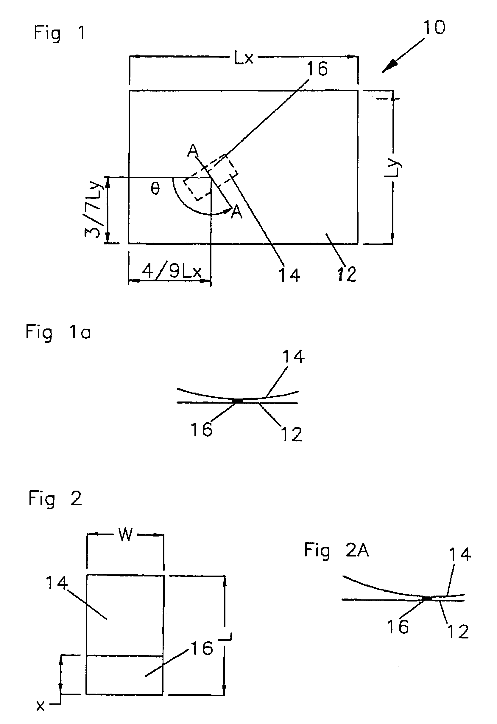
[0085]FIG. 1 shows a panel-form loudspeaker (10) comprising an acoustic radiator in the form of a resonant panel (12) and a transducer (14) mounted on the panel (12) to excite bending-wave vibration in the panel (12), e.g. as taught in WO97 / 09842 and U.S. Pat. No.08 / 707,012. Resonant bending wave panel speakers as taught in WO97 / 09842 and U.S. Pat. No. 08 / 707,012 are known as DM or DML speakers. The transducer (14) is mounted off-centre on the panel on a mount (16) at a position which is at 4 / 9 ths of the panel length and 3 / 7 ths of the panel width. This is an optimum position for applying a force to the panel as taught by WO 97 / 09842 and U.S. Pat. No. 08 / 707,012.

[0086]The transducer (14) is a pre-stressed piezoelectric actuator of the type disclosed in U.S. Pat. No. 5,632,841 (International patent application WO 96 / 31333) and produced by PAR Technologies Inc under the trade name NASDRIV. Thus the transducer (14) is an active resonant element.

[0087]As shown in FIGS. 1 and 1a, the tr...


PUM


Abstract

A transducer (14) for producing a force which excites an acoustic radiator, e.g. a panel (12) to produce an acoustic output. The transducer (14) has an intended operative frequency range and comprises a resonant element which has a distribution of modes and which is modal in the operative frequency range. Parameters of the transducer (14) may be adjusted to improve the modality of the resonant element. A loudspeaker (10) or a microphone may incorporate the transducer.

Description

[0001]This application claims the benefit of provisional application Nos. 60 / 178,315, filed Jan. 27, 2000; 60 / 205,465, filed May 19, 2000; and 60 / 218,062, filed Jul. 13, 2000.TECHNICAL FIELD[0002]The invention relates to transducers, actuators or exciters, particularly but not exclusively transducers for use in acoustic devices, e.g. loudspeakers and microphones.BACKGROUND ART[0003]A number of transducer, exciter or actuator mechanisms have been developed to apply a force to a structure, e.g. an acoustic radiator of a loudspeaker. There are various types of these transducer mechanisms, for example moving coil, moving magnet, piezoelectric or magnetostrictive types. Typically, electrodynamic speakers using coil and magnet type transducers lose 99% of their input energy to heat whereas a piezoelectric transducer may lose as little as 1%. Thus, piezoelectric transducers are popular because of their high efficiency.[0004]There are several problems with piezoelectric transducers, for exa...

Claims


Application Information

Patent Timeline
IPC IPC(8): H04R25/00H04R7/04H04R1/00H04R1/02H04R1/22H04R7/00H04R9/00H04R15/00H04R17/00H04R19/01
CPCH04R1/028H04R7/045H04R17/00H04R2499/13H04R7/00H04R15/02
Inventor BANK, GRAHAMHARRIS, NEILCOLLOMS, MARTIN
Owner GOOGLE LLC
Learn More