Coarse wavelength division multiplexing system

a wavelength division and multiplexing technology, applied in the field of communication, can solve the problems of increasing the cost of the system, increasing the bandwidth of optical fibers, and increasing the data rate, and achieve the effect of maximizing the coverage of the optical communication network

Active Publication Date: 2006-12-12
FURAKAWA ELECTRIC NORTH AMERICA INC
View PDF2 Cites 14 Cited by
  • Summary
  • Abstract
  • Description
  • Claims
  • Application Information

AI Technical Summary

Benefits of technology

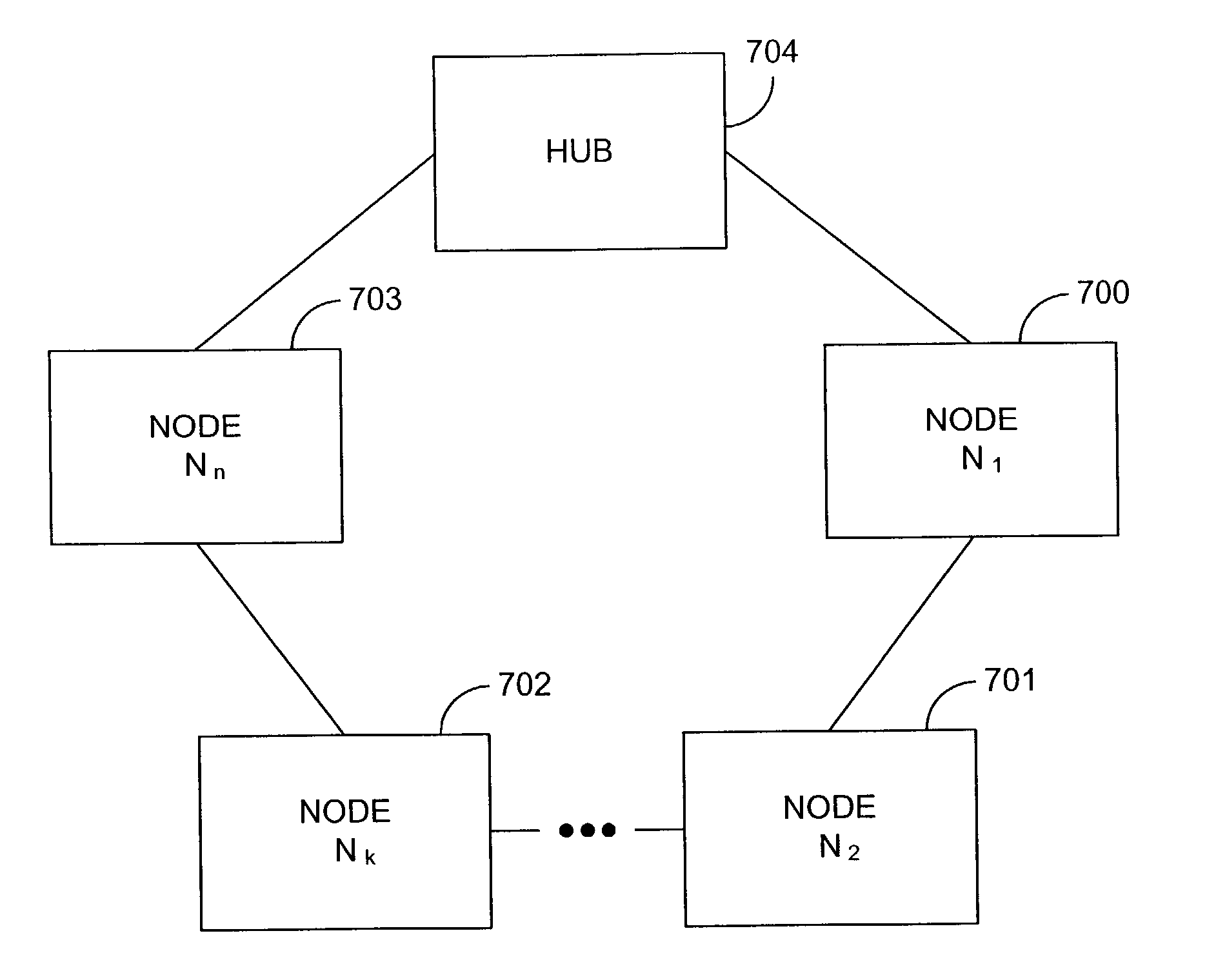
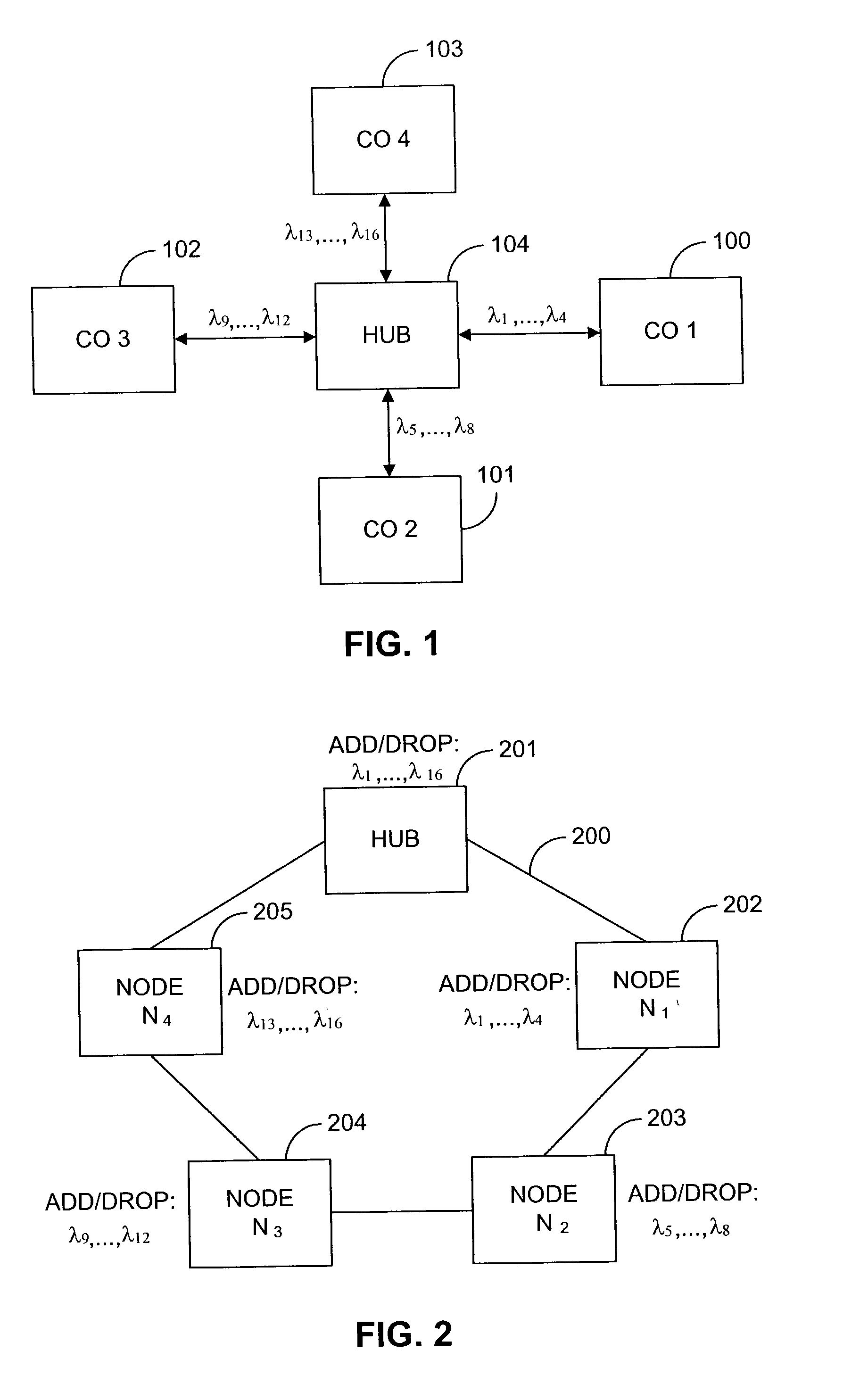
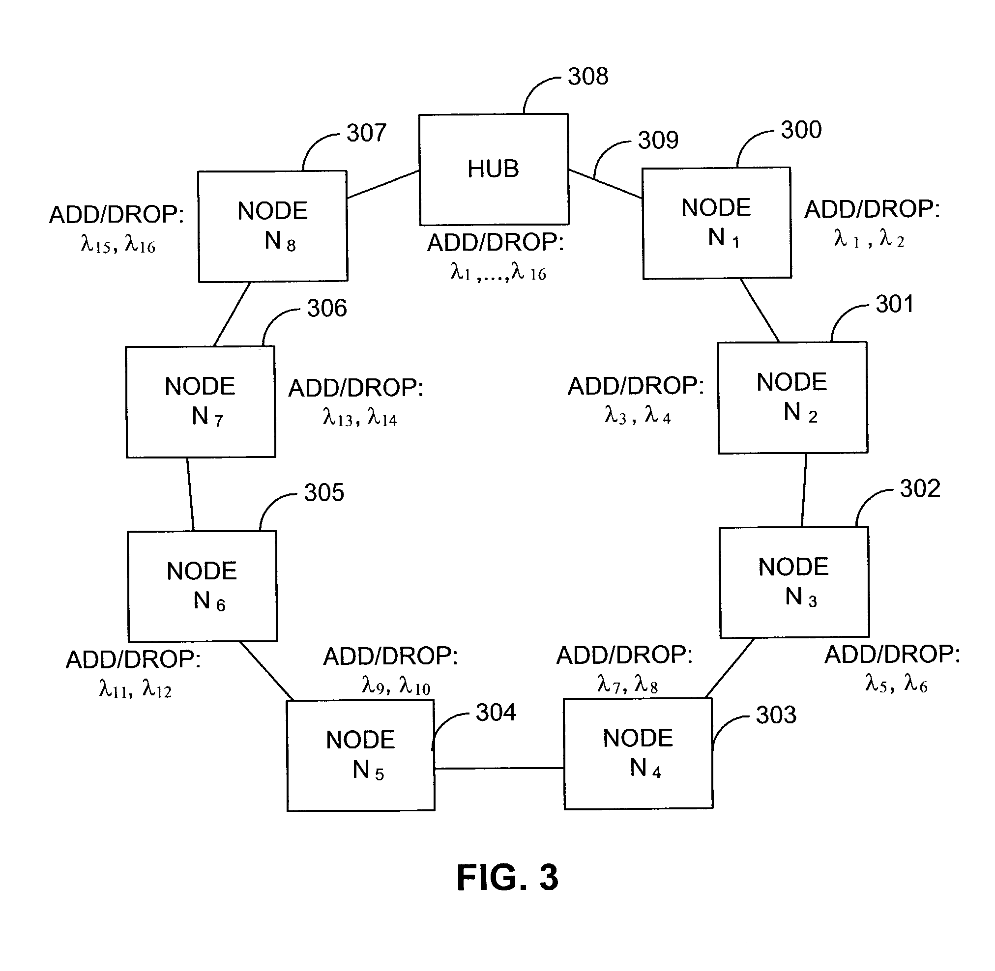
[0009]A method of the present invention for maximizing the coverage of an optical communication network includes creating an optical network comprising a plurality of nodes, and assigning a plurality of wavelength groups to the plurality of nodes based upon the ring loss and fiber loss of the optical network.

Problems solved by technology

Furthermore, optical fibers provide greater bandwidth than copper wires, which results in higher data rates.
Such highly selective filters increase the expense of the system.
Moreover, the narrow channel spacing requires high precision, cooled lasers which exhibit low wavelength drift and dispersion characteristics, thereby also increasing the expense of the system.

Method used


Image

  • Coarse wavelength division multiplexing system
  • Coarse wavelength division multiplexing system
  • Coarse wavelength division multiplexing system

Examples


Embodiment Construction

[0037]The invention now will be described more fully with reference to the accompanying drawings. The invention may, however, be embodied in many different forms and should not be construed as being limited to the embodiments set forth herein; rather, these embodiments are intended to convey the concepts and principles of the invention to those skilled in the art. Furthermore, all “examples” given herein are intended to be non-limiting.

[0038]CWDM is capable of enabling multi-wavelength optical systems to be introduced into metropolitan (metro) networks inexpensively. Compared to DWDM, CWDM achieves cost reduction via the use of cheaper wide-channel spacing filters. These wide-channel spacing filters allow less expensive non-cooled lasers to be used in CWDM systems. However, because CWDM systems are non-amplified, the attainable system reach currently is severely limited by filter and fiber attenuation losses.

[0039]The wavelength assignment system of the present invention presents a ...


PUM


Abstract

In a ring network comprising a plurality of nodes and a 16 channel coarse wavelength-division multiplexing (CWDM) plan, a technique is disclosed for adding and dropping channels that reduces the maximum attenuation loss that any channel encounters—thereby enabling longer rings to be constructed without using optical amplifiers in the ring. The 16 channels are typically distributed between the wavelengths 1310–1610 nm with 20 nm separation between channels. It is obscured that glass fibers have gradually decreasing loss at longer wavelengths in this band. The network includes a hub and several nodes that are interconnected by optical fibers in a ring configuration, where distance from the hub is the minimum value measure in either the clockwise or counterclockwise direction. Channels are assigned to the various nodes based on their wavelength. The channels whose wavelengths are near 1310 nm are assigned to nodes that are progressively closer to the hub.

Description

TECHNICAL FIELD OF THE INVENTION[0001]The present invention is generally related to communications and, more particularly, to optical communication networks.BACKGROUND OF THE INVENTION[0002]Optical communication networks have increasingly been seen as the solution to many bandwidth problems that occur fairly frequently on other networks. Optical communication networks use optical fibers, which are typically less susceptible to external noise than other media and are typically cheaper to make than copper wire. Furthermore, optical fibers provide greater bandwidth than copper wires, which results in higher data rates. Typically, data streams that are transferred through a communications system can be divided from each other according to several different protocols. In optics, the data streams are often separated by wavelength. Protocols that separate data based on wavelength are generally referred to as wavelength division multiplexing (WDM) protocols.[0003]WDM in fiber optics is typi...

Claims


Application Information

Patent Timeline
Patent Type & Authority Patents(United States)
IPC IPC(8): H04J14/00H04J14/02
CPCH04J14/0227H04J14/0283H04J14/0246H04J14/0206H04J14/0209H04J14/0213
Inventor UFONGENE, CHARLES
Owner FURAKAWA ELECTRIC NORTH AMERICA INC
Why Eureka
Try Eureka