
Position pointing device

a technology of position pointing and pointing device, which is applied in the direction of electromechanical unknown time interval measurement, instruments, horology, etc., can solve the problems of inability to provide a position pointing device that serves purposes, difficulty in changing the type of pointing device information or the number of bits to be returned, and the above-described position pointing device has some problems, so as to achieve battery-less operation and low power

Inactive Publication Date: 2006-12-12
WACOM CO LTD
View PDF3 Cites 18 Cited by
  • Summary
  • Abstract
  • Description
  • Claims
  • Application Information

AI Technical Summary

Benefits of technology

[0008]Accordingly, an object of the present invention is to provide a technology that can achieve a battery-less operation with low power transmitted from a tablet.
[0009]Another object of the present invention is to provide a technology for allowing battery-less position pointing devices for various applications to be put into commercial production with flexibility at a lower design cost in a short period of time.
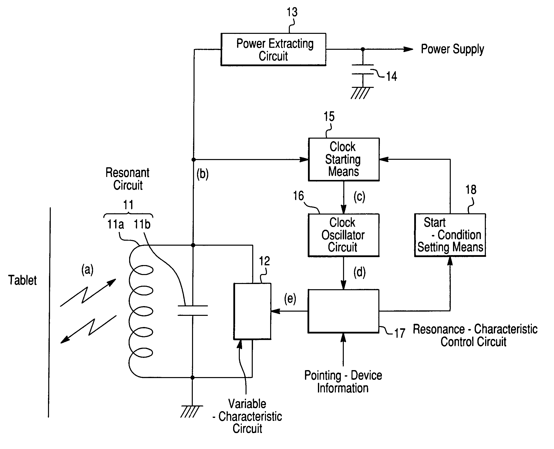
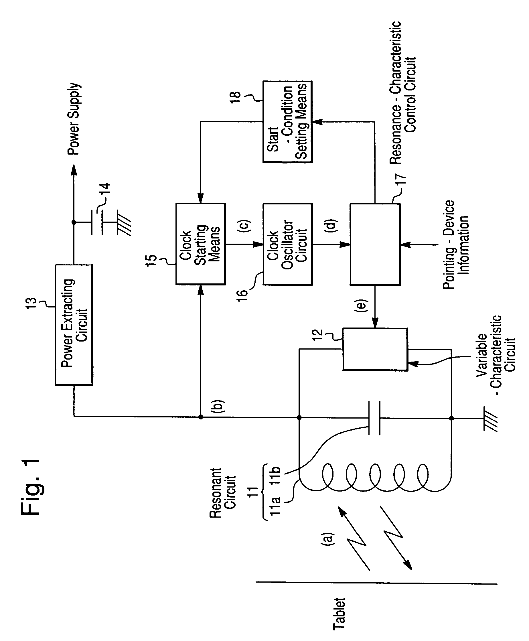
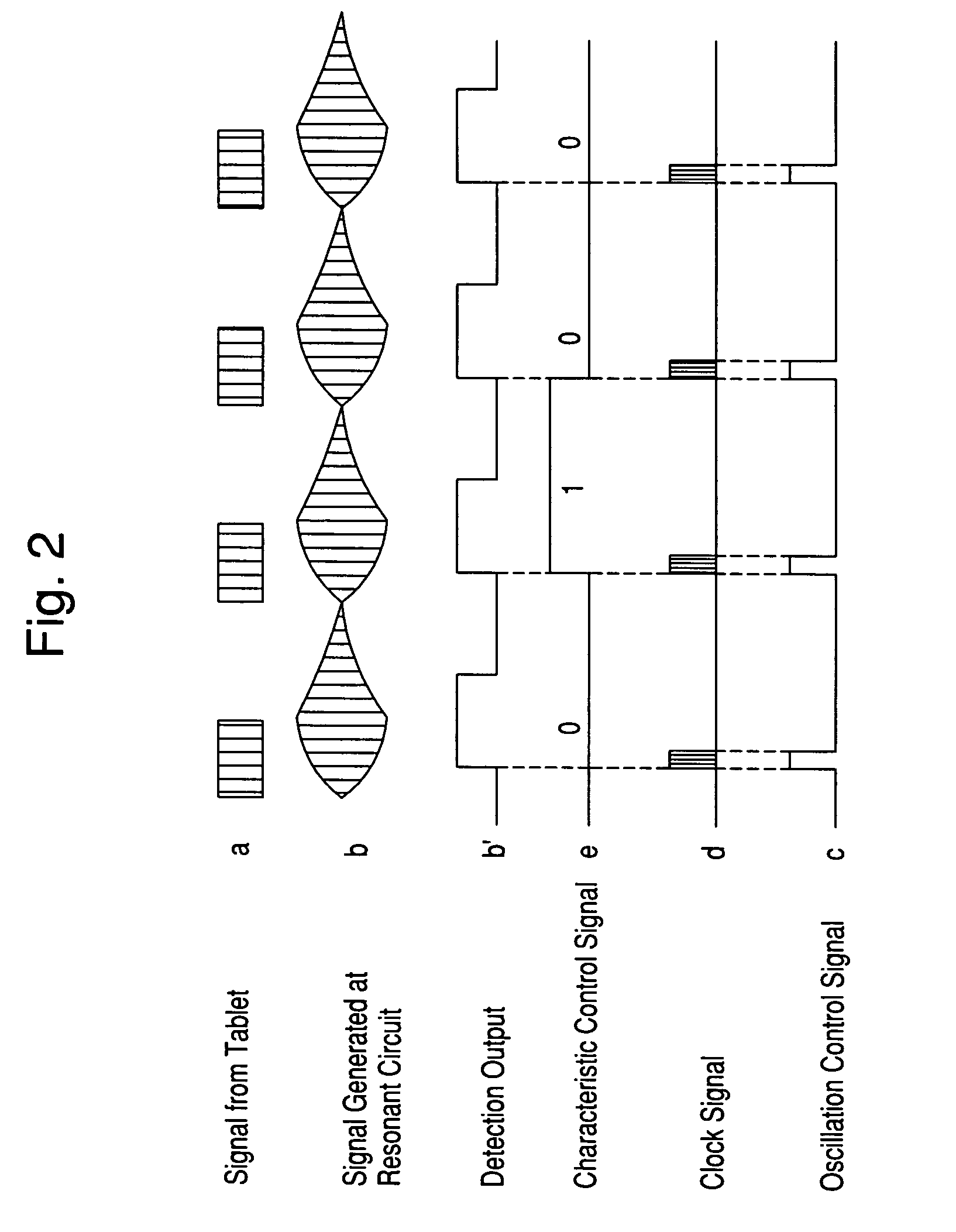
[0011]As described above, according to the present invention, the clock oscillator circuit can be put into an operation state in only a period in which the resonance-characteristic control circuit needs to be operated and can be put into a stopped state in other periods. This arrangement can reduce power consumption by an amount corresponding to the period of a stopped state. This can achieve a battery-less operation even with lower power transmitted from a tablet.
[0012]In this case, as the resonance-characteristic control circuit, a microprocessor (CPU) may be used that includes a ROM, RAM, and a clock oscillator circuit and that operates in accordance with a program that has been created in advance and that has been written into the ROM. This arrangement can significantly facilitate changes in functions of the position pointing device and in the amount of data to be returned, by changing the program. Further, the arrangement can put position pointing devices for various applications into commercial production with flexibility at a lower design cost in a short period of time.
[0025]As described above, the present invention can reduce the period in which the resonance-characteristic control circuit 17 operates and can significantly reduce the average of consumed current. This can provide a battery-less position pointing device even with less power transmitted from a tablet. In addition, a microprocessor (CPU) may be used for the resonance-characteristic control circuit 17. With such a configuration, changing a program written to the CPU can facilitate a change in the functions of the position pointing device.

Problems solved by technology

The above-described position pointing devices have some problems.
This makes it difficult to change the type of pointing-device information or the number of bits to be returned and also makes it impossible to provide a position pointing device that serve purposes.
Additionally, cost for design is high.

Method used


Image

  • Position pointing device
  • Position pointing device
  • Position pointing device

Examples


first embodiment

Extensions of First Embodiment

[0072]FIG. 4 shows a state when the switches S1, S4, and S5 are operated. A tablet having a configuration for detecting a change in the resonant frequency of a position pointing device as a change in signal phase may be used for the tablet for use in the present embodiment. Examples include those described in Patent Document 1 or a second embodiment of Japanese Unexamined Patent Application Publication No. 8-171448.

[0073]In the present embodiment, an oscillator circuit employing charging / discharging operations performed by the resistor 28 and the capacitor 29 shown in FIG. 3 is used in order to allow quick start and stop of the CPU 27. Specific examples of such an oscillator circuit include the configuration shown in FIG. 6.

[0074]While a description in the present embodiment is given of an example in which information corresponding to the operations of the five switches S1 to S5 is returned, the embodiment is not limited five switches. Further, informat...

second embodiment

Extensions of Second Embodiment

[0098]FIG. 8 shows a case in which data to be returned has “1, 0, 0, 0, 1, 1, 0, 1” from the top, and the data is returned from the bottom (D0). The data, however, may be returned from the top.

[0099]Further, while the pressure-sensitive resistance element is used to detect a continuous amount in the present embodiment, another sensor may be used.

[0100]While only values detected by the pressure-sensitive resistance element are used as data to be returned, a switch or the like may be provided so that a value obtained from the switch is returned together or an ID code or the like may be returned together.

[0101]For the tablet for use in the present embodiment, one having a configuration for detecting information of an operation or the like as a signal level in accordance with the presence / absence of a signal from the position pointing device may be used. Examples include those having configurations disclosed in a first embodiment of Japanese Unexamined Pat...

third embodiment

Extensions of Third Embodiment

[0142]Although the two-bit command is transmitted subsequent to the long transmission of 1000 μs in the present embodiment, the order may be reversed. In such a case, the arrangement may be such that the first start of the CPU 45 is initiated in response to the rising edge of a signal from the terminal P1 rather than the terminal P2.

[0143]In addition, a command from the tablet is not limited to two bits, and a command having more bits may be used so that more types of information can be returned.

[0144]In the present embodiment, in order to detect the time of charging performed by the variable capacitor 48 and the resistor 49, the number of signal waves generated in the resonant circuit 11 is counted. For this technology, one disclosed in Japanese Unexamined Patent Application Publication No. 7-176672 (U.S. Pat. No. 5,679,930) may be used. A clock signal generated by the CPU 45 may be used to detect the time, instead of the signal generated by the resona...


PUM


Abstract

A position pointing device includes a resonant circuit, a resonance-characteristic control circuit for controlling characteristics of the resonant circuit in accordance with pointing-device information at timing synchronized with at least part of an electromagnetic wave that is intermittently transmitted from a tablet and for returning the pointing-device information to the tablet, a clock oscillator circuit for generating a clock signal for driving the resonance-characteristic control circuit, and clock starting means for stopping an operation of the clock oscillator circuit when a start condition is set and for starting the operation of the clock oscillator circuit when the resonant circuit generates a signal specified by the start condition. The position pointing device further includes start-condition setting means for setting the start condition in the clock starting means at timing in accordance with an operation of the resonance-characteristic control circuit.

Description

CROSS-REFERENCE TO RELATED APPLICATIONS AND CLAIM TO PRIORITY[0001]This application claims the benefit under 35 U.S.C. § 119 of application no. 2003-170960, file Jun. 16, 2003 in Japan, the disclosure of which is incorporated herein by reference.BACKGROUND OF THE INVENTION[0002]1. Field of the Invention[0003]The present invention relates to improvements in a position pointing device used for an apparatus for detecting a position indicated by the position pointing device utilizing electromagnetic induction.[0004]2. Description of the Related Art[0005]Conventionally, position pointing devices have been known which control characteristics of a resonant circuit provided therein in accordance with data of a switch or a writing pressure at timing synchronized with an electromagnetic wave intermittently transmitted from a tablet and which return the resulting information to the tablet. Examples include Patent Document 1 (Japanese Unexamined Patent Application Publication No. 3-189716), Pat...

Claims


Application Information

Patent Timeline
Patent Type & Authority Patents(United States)
IPC IPC(8): G06F15/00G06F3/046G06F1/32G06F3/033
CPCG06F1/3203G06F1/3237G06F1/325G06F3/046Y02B60/1221Y02D10/00
Inventor KATSURAHIRA, YUJI
Owner WACOM CO LTD
Learn More