
Kink resistant endovascular graft

a technology of endovascular grafts and kinks, which is applied in the field of kink-resistant endovascular grafts, can solve the problems of negative impact on the overall axial compliance of the device, and achieve the effect of maintaining kink resistan

Inactive Publication Date: 2006-12-19
BOSTON SCI CORP
View PDF67 Cites 87 Cited by
  • Summary
  • Abstract
  • Description
  • Claims
  • Application Information

AI Technical Summary

Benefits of technology

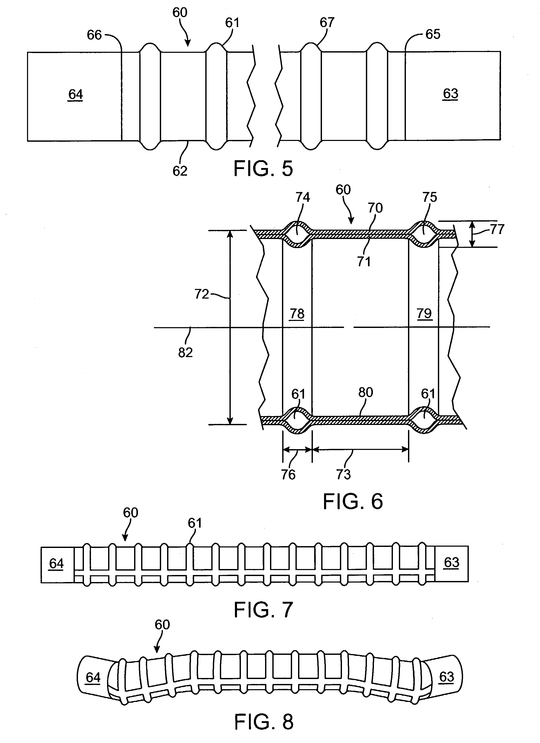
[0006]Embodiments of the invention are directed to configurations of tubular or bifurcated intracorporeal structures and devices, such as endovascular grafts and stent-grafts, which have radial support member configurations that confer kink resistance to the intracorporeal device upon bending. Embodiments of radial support members may include circumferential radial support members, helical radial support members and the like. The radial support members may be inflatable in some embodiments. By carefully selecting the size, configuration and spacing of the radial support members, kink resistance may be improved while the negative impact on other parameters of the intracorporeal device may be reduced.
[0007]Kink resistance is enhanced generally by decreasing the longitudinal spacing between radial support members; however, spacing that is too small may negatively impact the overall axial compliance of the device and may require excess fill material for device embodiments that include inflatable radial support members such as circumferential inflatable channels, helical inflatable channels or the like.
[0011]In some embodiments, an endovascular graft may have longitudinal sections that are tubular. The longitudinal thickness of the circumferential inflatable channels or helical inflatable channel may be about 10 to about 30 percent of an outer transverse dimension of the tubular sections with the circumferential inflatable channel or helical inflatable channel in an expanded state. The inflatable channels may be inflated with an internal inflation pressure of about 3 to about 25 psi in some embodiments in order to provide compliance and maintain kink resistance.

Problems solved by technology

Kink resistance is enhanced generally by decreasing the longitudinal spacing between radial support members; however, spacing that is too small may negatively impact the overall axial compliance of the device and may require excess fill material for device embodiments that include inflatable radial support members such as circumferential inflatable channels, helical inflatable channels or the like.

Method used


Image

  • Kink resistant endovascular graft
  • Kink resistant endovascular graft
  • Kink resistant endovascular graft

Examples


Embodiment Construction

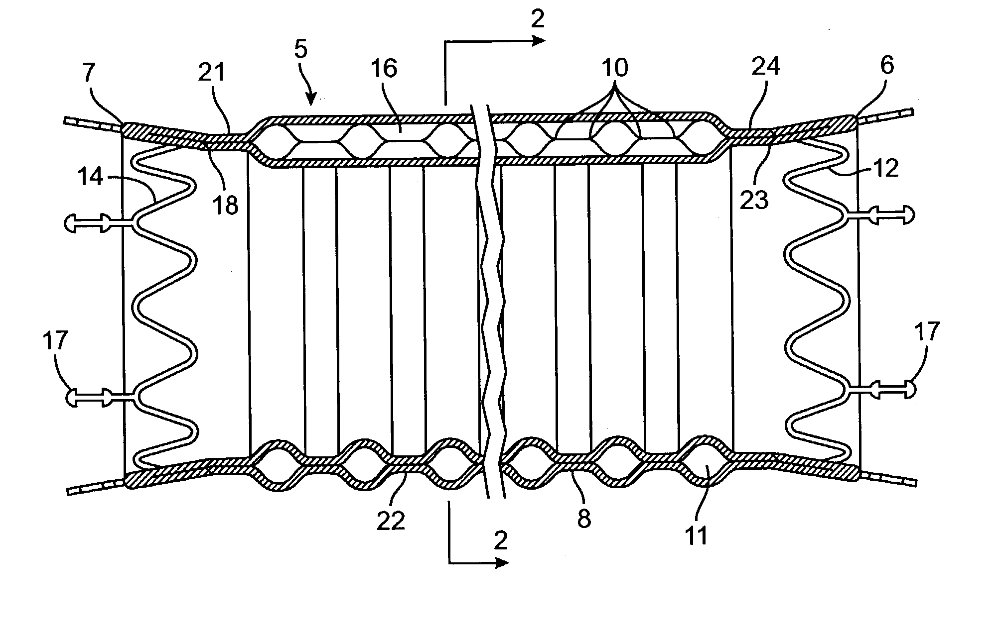
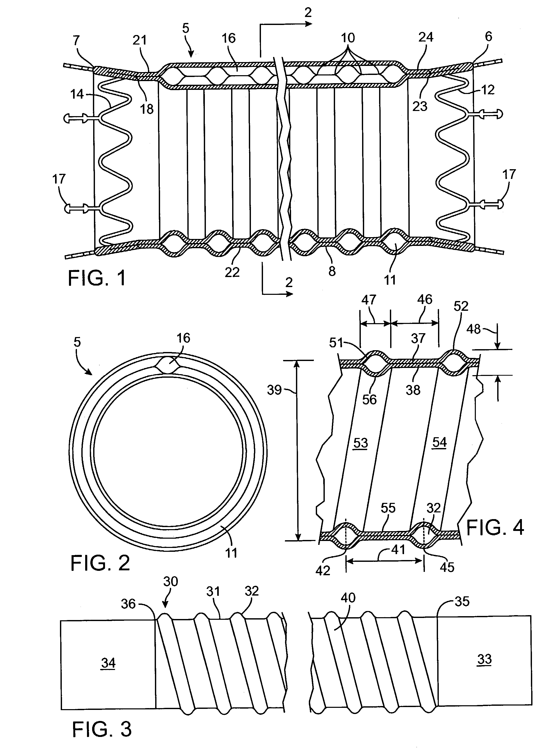
[0029]FIGS. 1 and 2 schematically show an embodiment of an endovascular graft assembly 5. The endovascular graft assembly 5 has a graft body section 8 having a generally tubular configuration with a proximal portion 6, a distal portion 7, and circumferential radial support members in the form of circumferential inflatable channels 11 disposed on body section 8 and shown in an expanded state. The circumferential inflatable channels 11 are integrally formed in the body section 8 by seams 10 formed in the body section 8. A longitudinal inflatable channel 16 communicates with the circumferential inflatable channels 11.

[0030]A proximal connector member 12 may be embedded within multiple layers of graft body section 8 in the vicinity of graft body section proximal portion 6. A distal connector member 14 may also be embedded within multiple layers of graft body section 8 in the vicinity of graft body section distal portion 7.

[0031]One or more expandable members or stents (not shown) may be...


PUM


Abstract

An intracorporeal device, such as an endovascular graft, having a tubular section with circumferential or helical radial support members. The radial support members may be inflatable channels which support the tubular structure of the graft and which are appropriately sized and longitudinally spaced to prevent or reduce kinking of the tubular structure upon bending of the tubular structure.

Description

BACKGROUND OF THE INVENTION[0001]Embodiments of the device and method discussed herein relate to a system and method for manufacturing intracorporeal devices used to replace, strengthen, or bypass body channels or lumens of patients; in particular, those channels or lumens, such as the abdominal or thoracic aorta, that have been affected by conditions such as aneurysmal disease.[0002]Existing methods of treating such aneurysms include invasive surgical methods with graft placement within the aorta as a reinforcing member of the artery. Although improvements in surgical and anesthetic techniques have reduced perioperative and postoperative morbidity and mortality, significant risks associated with surgical repair (including myocardial infarction and other complications related to coronary artery disease) still remain.[0003]Due to the inherent hazards and complexities of such surgical procedures, various attempts have been made to develop alternative repair methods that involve the en...

Claims


Application Information

Patent Timeline
Patent Type & Authority Patents(United States)
IPC IPC(8): A61F2/06A61F2/02
CPCA61F2/06A61F2/07A61F2002/072A61F2002/8486A61F2250/0003A61F2/89A61F2002/075
Inventor KARI, STUART ECHOBOTOV, MICHAEL V.
Owner BOSTON SCI CORP
Learn More