Rotor of reluctance motor

a reluctance motor and rotor technology, applied in the direction of synchronous motors, magnetic circuit rotating parts, magnetic circuit shape/form/construction, etc., can solve the problems of unbalanced rotor rotation, difficult to adhere the rotor to the axis, and the inability of humans to manually insert the rotor into the axis, so as to reduce the amount of unbalance of the rotor

Active Publication Date: 2006-12-19
OKUMA CORP
View PDF10 Cites 8 Cited by
  • Summary
  • Abstract
  • Description
  • Claims
  • Application Information

AI Technical Summary

Benefits of technology

[0009]The present invention advantageously solves the problem that, when the rotor is fixed to the axis by adhesion, a clearance between the rotor inner circumference and the axis outer circumference is increased to cause an amount of unbalance of the rotor and, when the rotor is fixed to the axis by “plunge-in” on the other hand, such unbalance is reduced but the stress by the “plunge-in” causes the breakage of the rotor.
[0012]Use of the present invention enables “plunge-in” of the rotor to the columnar axis at the projection part, even in the case of a rotor of a reluctance motor in which a plurality of slits are provided to provide a plurality of magnetic paths, to reduce the positional displacement of the rotor and the columnar axis, thereby reducing the amount of unbalance of the rotor. Furthermore, the projection is provided in the direction of the magnetic pole, and thus the stress caused by a “plunge-in” process can be applied to the magnetic path in the direction of the magnetic pole to disperse stresses that would have been concentrated if no plunge-in were used. As a result, the connection part can have a reduced thickness and torque and output generated in the electric motor can be increased.

Problems solved by technology

As a result, the rotor cannot be manually inserted into the axis by a human and a machine such as a hydraulic press is used to apply sufficient force in the axis direction to insert the rotor to the axis, thereby fixing the rotor to the axis by a frictional force caused between the rotor and the axis.
This clearance causes the rotor to rotate in an unbalanced manner.
Specifically, when the rotor is adhered to the axis, it is very difficult to adhere the rotor to the axis in such a manner that the clearance between the rotor and the axis is constant at any point in the rotation direction.
Such a clearance having a significant large size causes, when the rotor is adhered to the axis in a off-centered manner, the rotor to be enormously unbalanced.
However, correction of such an excessively large amount of unbalance is very difficult.
As a result, the amount of unbalance caused by the “plunge-in” method is very small compared to the adhesion method.
However, when a reluctance motor has a rotor in which a plurality of slits for providing a magnetic pole are provided, another problem results, as will be described with reference to FIG. 6, which is an enlarged view of a portion of FIG. 5.
The “plunge-in” method inserts the rotor to the axis while deforming the rotor inner circumference, thus applying an enormously large force to the rotor inner circumference.
If the reluctance motor has a rotor in which slits are provided, the existence of the slits weakens the entire structure with respect to centrifugal force.
This stress exceeds a limitation of allowable stress of the material, thus breaking the connection part 2D.
Thus, increasing the outer diameter of the rotor 1 leads to a decline in the generated torque and output.
On the other hand, increasing the thickness of the connection part leads directly to an increase in the leakage of magnetic flux and thus also to a decline of generated torque and output.
As described above, the “plunge-in” method to fix the rotor to the axis requires a particular part to have an increased thickness for reinforcement, thus causing a decline in the characteristics of the electric motor.

Method used


Image

  • Rotor of reluctance motor
  • Rotor of reluctance motor
  • Rotor of reluctance motor

Examples


Embodiment Construction

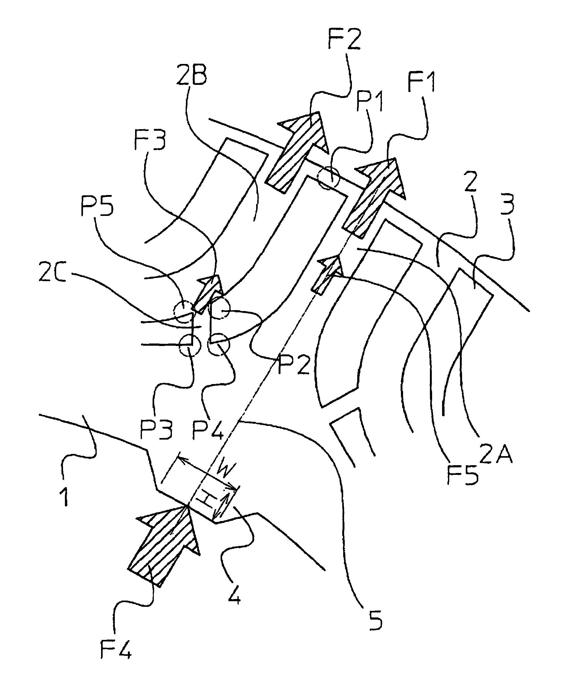
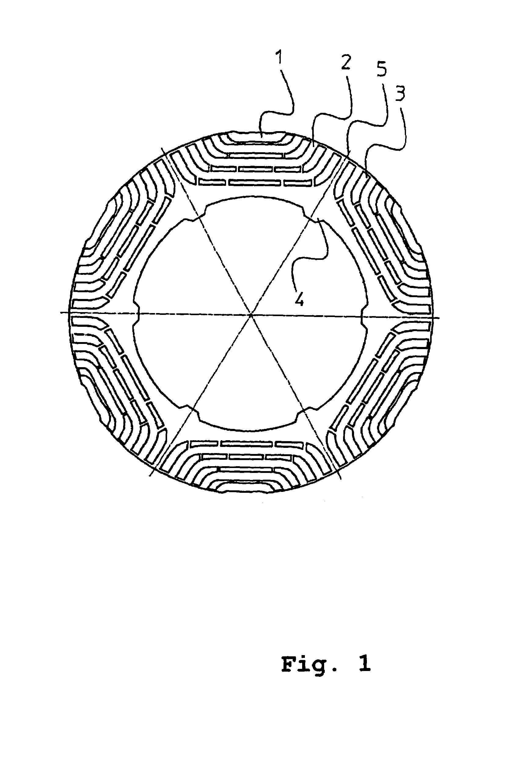
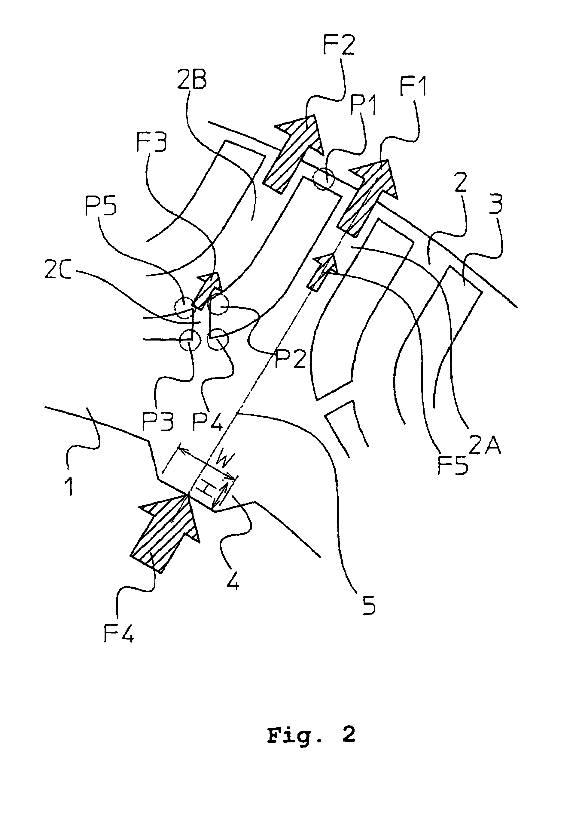
[0020]FIG. 1 is a cross-sectional view of a rotor of a reluctance motor of the present invention. FIG. 1 shows a rotor 1, a magnetic path 2, a slit 3, and a projection 4 which is a feature of the present invention. As shown in FIG. 1, in the rotor 1 are provided a plurality of slits 3 that constitute the magnetic path 2 and a magnetic pole center 5. FIG. 2 is an enlarged view of the vicinity of the magnetic pole in FIG. 1. As shown in FIG. 2, each projection 4 is provided in the direction of the radius of each magnetic pole center 5. The projection 4 has a width W of about few mm and a height H of about few μm to a few dozen μm. In FIG. 1 and FIG. 2, although the actual size of the projection 4 is significantly smaller than that of the rotor 1, only the projection 4 is conveniently illustrated to be larger so that the shape thereof can be clearly understood.

[0021]The rotor 1 in which the projections 4 are provided at the positions as described above has an inner circumference (where...


PUM


Abstract

A plurality of projections are provided abutted with an outer circumference of a columnar axis inserted to an inner circumference of a rotor. The projections are provided in the direction of a magnetic pole in the rotor. When the rotor is fixed to the columnar axis, the projection parts are fixed by “plunge-in” and the other rotor inner circumference parts have an uniform clearance to the columnar axis. The clearance is filled with an adhesive agent, thereby fixing the rotor to the columnar axis.

Description

TECHNICAL FIELD[0001]The present invention relates to a rotor of a reluctance motor. In particular, the present invention relates to an improved structure for fixing a ring-shaped lamination rotor and a columnar axis.BACKGROUND ART[0002]An electric motor has a rotor and an axis that are frequently provided as separate members. When they are provided as separate members, it is necessary to fix the rotor to the axis during assembly. One convenentional method is one in which the rotor is fixed to the axis using an adhesive will be described with reference to FIG. 5. FIG. 5 shows an example of a conventional method for adhering a rotor of an electric motor to be fixed to an axis. FIG. 5 shows a rotor 1, an axis 6, and adhesive agent 7. When the rotor 1 is adhered to be fixed to the axis 6, there a certain clearance is generally provided between the inner circumference of the rotor 1 and the outer circumference of the axis 6 because both the inner circumference of the rotor 1 and the out...

Claims


Application Information

Patent Timeline
Patent Type & Authority Patents(United States)
IPC IPC(8): H02K1/00F01D1/36F03B5/00H02K1/28H02K17/00H02K19/10
CPCH02K1/246H02K1/28
Inventor YOKOCHI, TAKANORIYURA, MOTOZUMIKAWAI, YOICHI
Owner OKUMA CORP
Why Eureka
Try Eureka