Controlled current source; in particular for digital/analogue converters in continuous-time sigma/delta modulators

a current source and control technology, applied in the direction of code conversion, transmission system, instruments, etc., to achieve the effect of reducing the sensitivity to clock jitter

Inactive Publication Date: 2006-12-19
INTEL CORP
View PDF8 Cites 23 Cited by
  • Summary
  • Abstract
  • Description
  • Claims
  • Application Information

AI Technical Summary

Benefits of technology

[0015]The object of the present invention is achieved with the controlled current source described in claim 1. The claims 5, 7 and 11 describe a digital / analogue converter, a sigma / delta analog / digital converter and a method of operation, in which the proposed current source is utilized to reduce sensitivity to clock jitter.
[0020]The proposed implementation of a digital / analogue converter equipped with a controlled current source according to the present invention in a sigma / delta modulator is very simple as usual perhaps even already implemented current source digital / analogue converters including all the linearization techniques, single bit and multibit, can be employed. For clock jitter insensitive implementation, the falling flank must only be reproducibly provided, in the ideal case only once for the entire modulator. The current pulse supplied by the current source is largely independent of the common-mode-input voltage (VCM) of the integrator. Feedback due to the fluctuations VCM will, therefore only vary a little in the real implementation, which again results in improved jitter insensitivity.

Problems solved by technology

This signal flank must limit the current within a clock cycle to sufficiently small values so that any premature or delayed switching-off due to clock jitter causes a sufficiently small error in a downstream application which requires provision of constant current packages independent of clock jitter.

Method used


Image

  • Controlled current source; in particular for digital/analogue converters in continuous-time sigma/delta modulators
  • Controlled current source; in particular for digital/analogue converters in continuous-time sigma/delta modulators
  • Controlled current source; in particular for digital/analogue converters in continuous-time sigma/delta modulators

Examples


Embodiment Construction

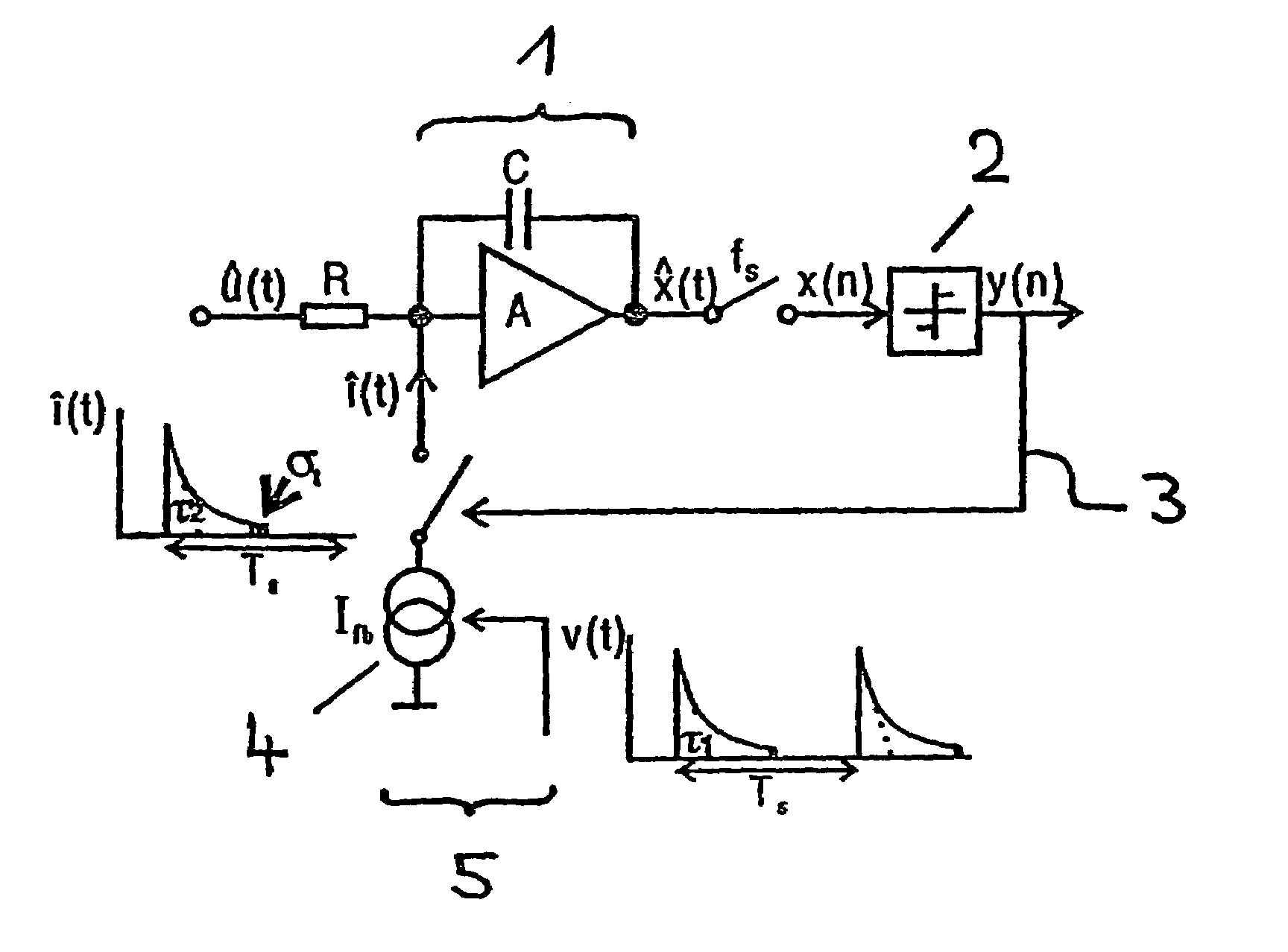
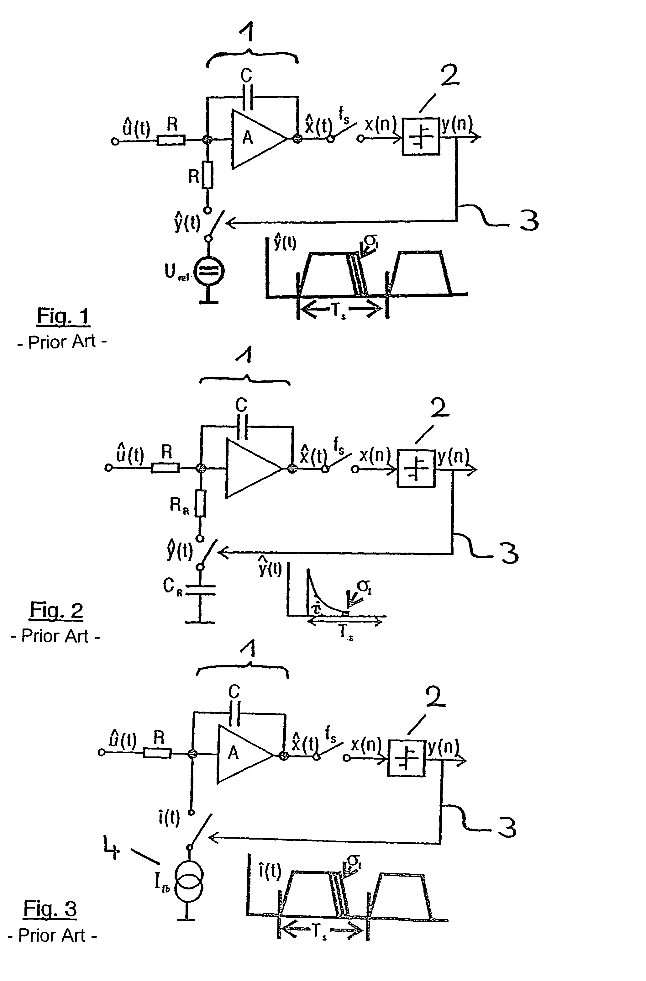
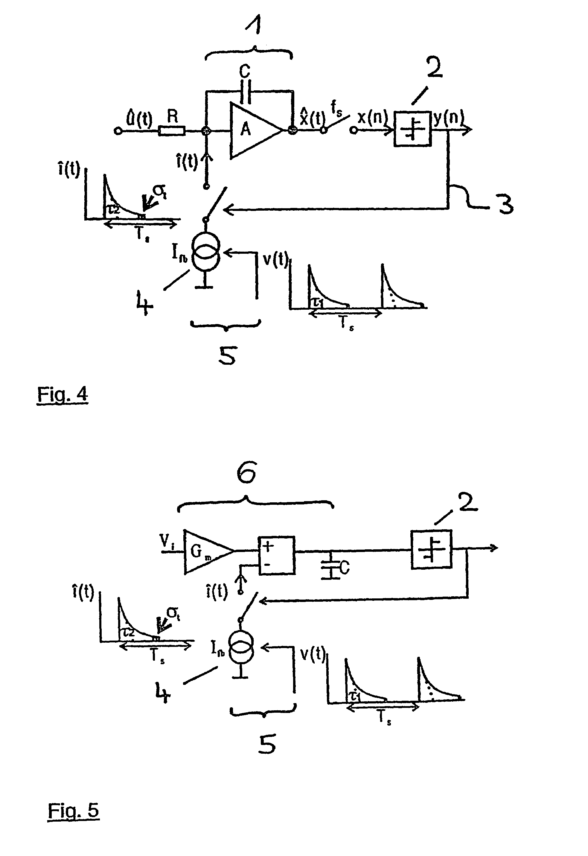
[0035]The embodiments of the known state-of-the-art sigma / delta modulators according to FIGS. 1 and 2 have already been described in detail in the introductory part of the summary of the invention. FIG. 3 shows the embodiment of a sigma / delta modulator in which the digital / analogue converter is provided with a current source 4 in the feedback branch. In this sigma / delta modulator as well, the input signal û(t) is superimposed via a resistance R at the input of the integrator 1 of the modulator with the feedback signal. The integrator 1 comprises here too an operating amplifier A and a capacitor C. The integrated output signal x^(t) is sampled by means of a clock frequency fs and the sampling signal x(n) is conveyed to a quantizer 2, which delivers a digital output signal y(n). This digital output signal is fed back via the digital / analogue converter to the input of the modulator. In this manner, the current source 4 is switched on and off dependent on the digital signal y(n) which a...


PUM


Abstract

The present invention relates to a controlled current source having a control input, in particular for digital / analogue converters in continuous-time sigma / delta modulators, having a current source (4) with a control input which generates an output current dependent on a control voltage applied to the control input, and having a controller (7) for converting a clock signal into a voltage signal, with the controller (7) being connected to the current source (4) in such a manner that the voltage signal is applied as a control voltage to the control input of the current source (4). The controller is designed to is designed to convert the clock signal into a voltage signal which has within a clock duration a reproducible curve ending with a falling flank. Using the present controlled current source in a digital / analogue converter in a feedback branch of a continuous-time sigma / delta modulator permits realizing a sigma / delta modulator which is essentially insensitive to clock jitter.

Description

[0001]This application is a 371 of PCT / DE03 / 03321 filed Oct. 7, 2003.TECHNICAL FIELD[0002]The present invention relates to a controlled current source, which generates an output current dependent on a control voltage applied at a control input, the controlled current source having a controller for converting a clock signal into a voltage signal. The controller is connected to the current source in such a manner that the voltage signal is applied to the control input of the current source as a control voltage. Furthermore, the invention relates to a digital / analogue converter with the controlled current source, to a sigma / delta analogue / digital converter having a continuous-time sigma / delta modulator with the digital / analogue converter as well as to a method of operation.[0003]In recent years, new technologies permitted distinctly improving sigma / delta analogue / digital converters as well as their main component, the sigma / delta modulator, with regard to resolution and conversion rate...

Claims


Application Information

Patent Timeline
Patent Type & Authority Patents(United States)
IPC IPC(8): H03M3/00
CPCH03M3/372H03M3/43H03M3/456
Inventor ORTMANNS, MAURITSMANOLI, YIANNOSGERFERS, FRIEDEL
Owner INTEL CORP
Why Eureka
Try Eureka