Low-power SRAM E-fuse repair methodology

a low-power sram and e-fuse technology, applied in the field of devices, can solve the problems of current implementations providing no methodology to power down one or more memory for low-power/leakage applications, and achieve the effect of significant leakage power savings and removal of system latency during memory and/or e-fuse farm module power-down

Active Publication Date: 2006-12-19
TEXAS INSTR INC
View PDF4 Cites 24 Cited by
  • Summary
  • Abstract
  • Description
  • Claims
  • Application Information

AI Technical Summary

Benefits of technology

[0006]To meet the above and other objectives, the present invention provides a method for substantially removing system latency during memory and / or E-fuse farm module power-down in a device that employs E-fuse farm technology. The method maintains power to the repair registers and minimal control logic in the memories, while all other circuitry can be either placed in a low power data retention mode, or completely powered off. There is no need to rescan the repair data from the E-fuse farm after one or more memories are powered back up. This provides dynamic power savings since there is no longer any need to idle the system to reload repair data. Since the E-fuse farm can be powered down after initial system power-up and repair data is loaded into the memories, there is also a significant leakage power savings.

Problems solved by technology

Current implementations thus provide no methodology to power down one or more memories for low power / leakage applications.

Method used


Image

  • Low-power SRAM E-fuse repair methodology
  • Low-power SRAM E-fuse repair methodology
  • Low-power SRAM E-fuse repair methodology

Examples


Embodiment Construction

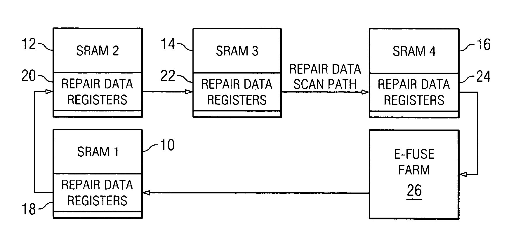
[0039]FIG. 1 is a diagram depicting a current E-fuse farm implementation. FIG. 1 shows a plurality of SRAM memory devices 10, 12, 14, 16, each containing its distinct set of repair data registers 18, 20, 22, 24, connected to an E-fuse farm 26. If power is cut to one or more memories 10, 12, 14, 16 and / or the E-fuse farm 26, the repair information will be lost and access to the memories will not be possible until the device is powered off and then on again to reload the repair data. The implementation shown in FIG. 1 thus provides no methodology to power down one or more memories for low power / leakage applications.

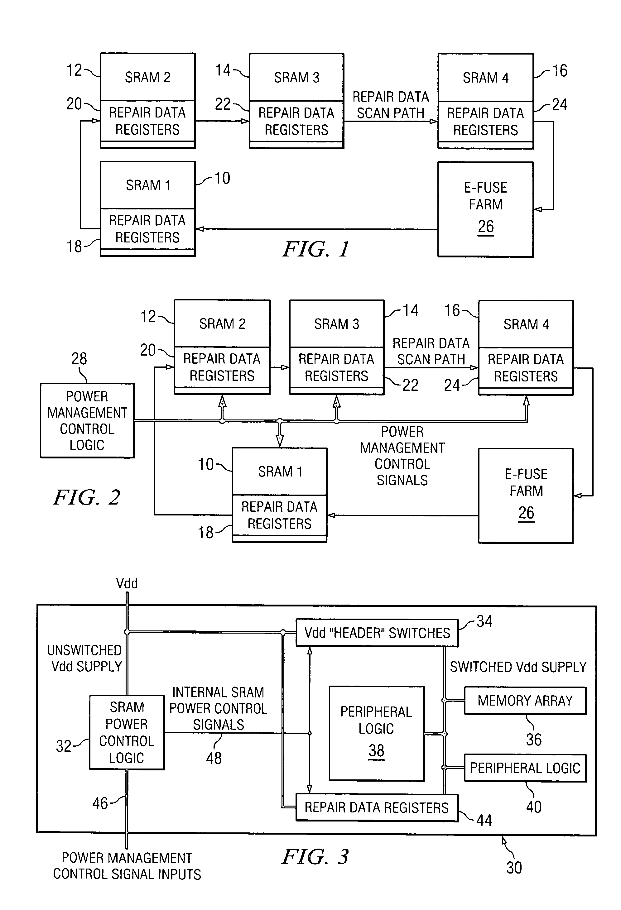
[0040]FIG. 2 is a diagram depicting a low power E-fuse farm implementation according to one embodiment of the present invention. The E-fuse farm implementation shown in FIG. 2 is similar to the implementation shown in FIG. 1, except the implementation shown in FIG. 2 can be seen to also employ power management control logic 28. The power management control logic 28 operates...


PUM


Abstract

A low power E-fuse repair methodology substantially removes system latency during memory and / or E-fuse farm module power-down in a device that employs E-fuse farm technology. The method maintains power to the repair registers and minimal control logic in the memories, while all other circuitry can be either placed in a low power data retention mode, or completely powered off. There is no need to rescan the repair data from the E-fuse farm after one or more memories are powered back up. This provides dynamic power savings since there is no longer any need to idle the system to reload repair data. Since the E-fuse farm can be powered down after initial system power-up and repair data is loaded into the memories, there is also a significant leakage power savings.

Description

BACKGROUND OF THE INVENTION[0001]1. Field of the Invention[0002]This invention relates generally to devices utilizing memories with repair capabilities, and more particularly to a method for substantially removing system latency during memory and / or E-fuse farm module power-down in a device that employs E-fuse farm technology.[0003]2. Description of the Prior Art[0004]Devices utilizing memories with repair capability require an E-fuse farm module be included on the device chip. The E-fuse farm contains the programmable fuse elements for storing the repair information as well as the control logic for programming and loading the repair information into the memories. The repair information is loaded into the memories from the E-fuse farm module upon device power-up via a serial scan chain path connecting the E-fuse farm and the memories. Once the repair information has been scanned into the memories, the E-fuse farm logic performs no additional functions and remains idle. In current im...

Claims


Application Information

Patent Timeline
Patent Type & Authority Patents(United States)
IPC IPC(8): G06F11/00G06F12/16G06F11/14G11C29/00
CPCG11C29/802
Inventor TRAN, TAM MINHJAMISON, GEORGE B.
Owner TEXAS INSTR INC
Why Eureka
Try Eureka