
Method of producing a gas generator housing part, gas generator including such housing part and gas bag module

a technology of gas generator and housing part, which is applied in the direction of non-electric welding apparatus, domestic applications, applications, etc., can solve the problems of more than compensating, prolonging welding time,

Active Publication Date: 2006-12-26
TRW AIRBAG SYST
View PDF17 Cites 3 Cited by
  • Summary
  • Abstract
  • Description
  • Claims
  • Application Information

AI Technical Summary

Benefits of technology

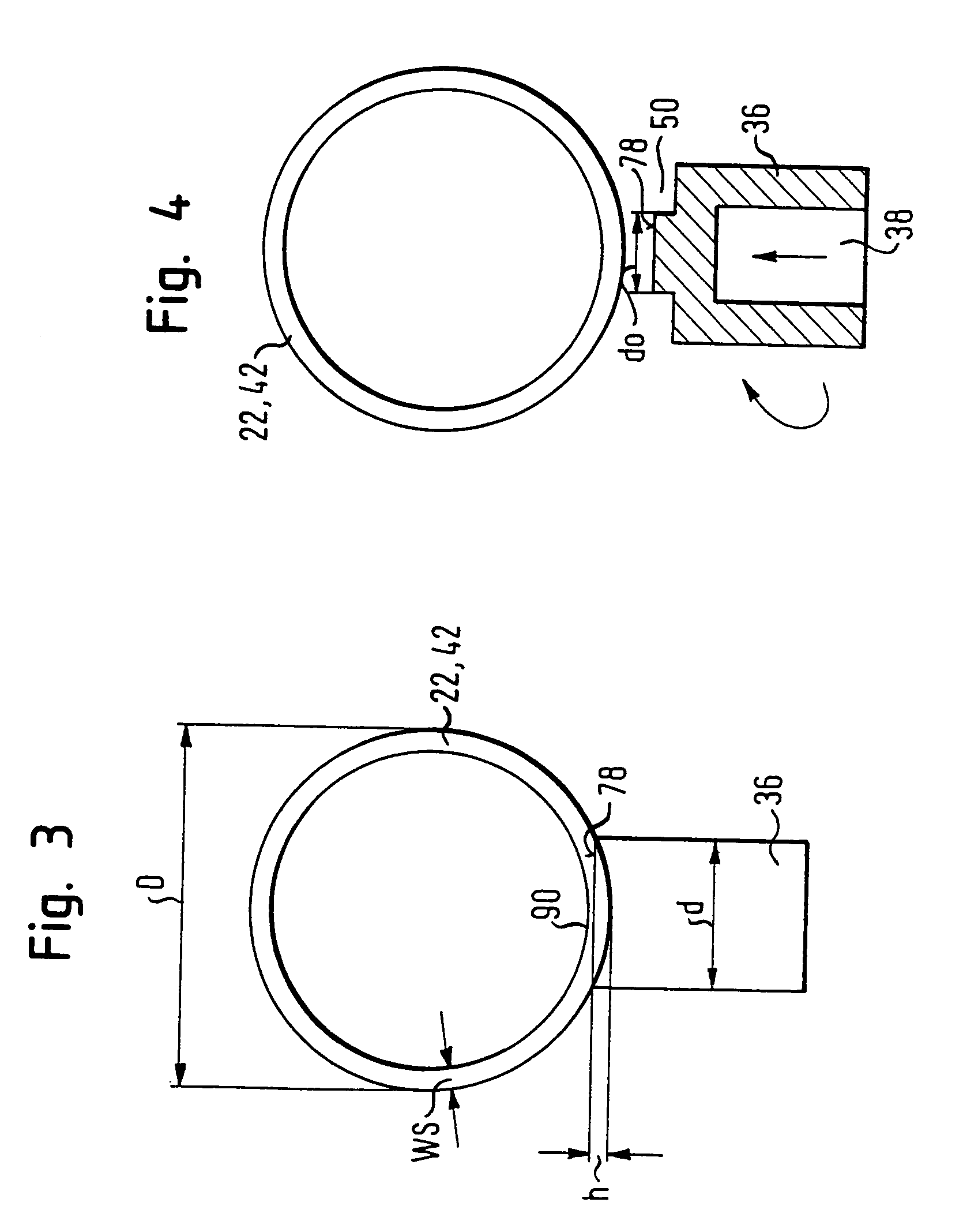
[0011]The method according to the invention provides a fine coordination of various parameters, which for the first time allow a relatively thick connecting piece to be laterally mounted to a thin-walled tube by friction welding. This welding process usually takes place in that the connecting piece is turned and then pressed radially against the peripheral wall of the tube. The friction depth is to be less than 80% of the wall thickness, preferably approximately two thirds of the wall thickness, so that on the inner face of the tube a wall section still remains which can offer a sufficient resistance to the radial action of force by the connecting piece.
[0013]A further surprise is the finding that the tube is preferably to remain non-machined on the welding surface before the welding process. This means that the tube is not machined or pressed flat in the region of the welding surface, i.e. the contact surface between the connecting piece and the outer surface of the tube, in order to provide as precise and large a contact surface as possible between the connecting piece, which is to be welded on the end face, and the peripheral wall. It is merely advantageous to clean the outside of the tube in the region of the welding surface. Thus, it is the flat end face of the connecting piece which meets the curved outer surface of the tube. Due to the tube being non-machined in the region of the welding surface, however, the peripheral wall has a higher stability in this region than in the machined state and can offer a greater resistance to the radial force which is exerted on it by the connecting piece. Although the contact surfaces are therefore less large and are aligned to each other less precisely, which can result in a longer welding time, this disadvantage is surprisingly more than compensated by the greater stability of the peripheral wall.

Problems solved by technology

Although the contact surfaces are therefore less large and are aligned to each other less precisely, which can result in a longer welding time, this disadvantage is surprisingly more than compensated by the greater stability of the peripheral wall.

Method used


Image

  • Method of producing a gas generator housing part, gas generator including such housing part and gas bag module
  • Method of producing a gas generator housing part, gas generator including such housing part and gas bag module
  • Method of producing a gas generator housing part, gas generator including such housing part and gas bag module

Examples


Embodiment Construction

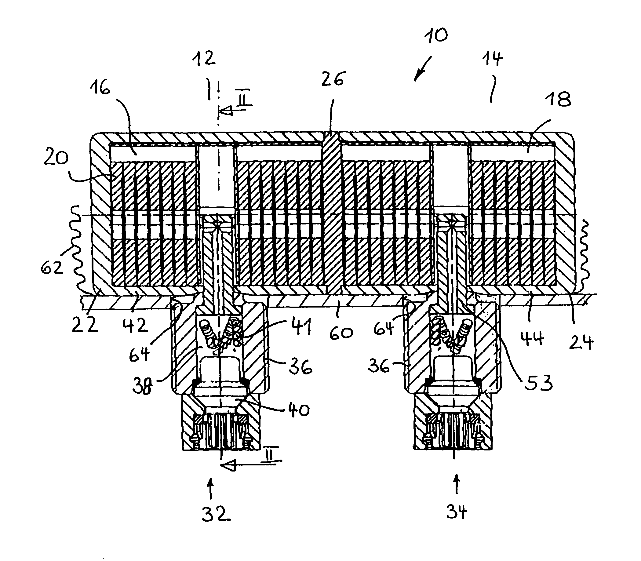
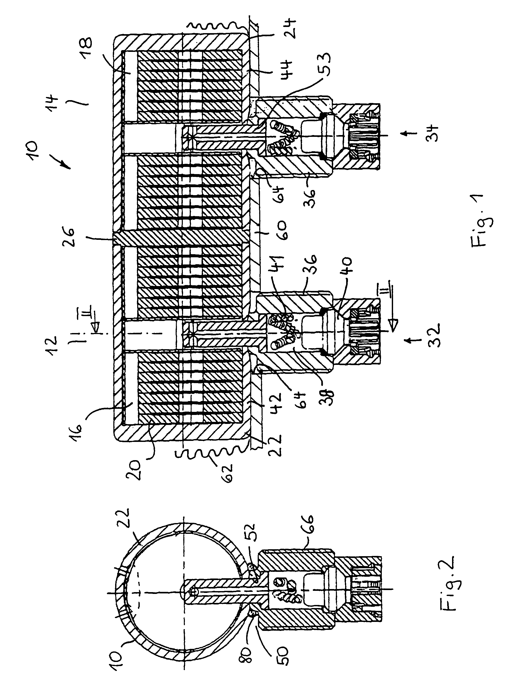
[0024]In FIG. 1 a two-stage tubular gas generator 10 is illustrated. The stages 12 and 14 are defined by two separate combustion chambers 16 and 18, respectively, which are filled with disc-shaped pyrotechnic solid propellant 20. The cylindrical outer housing of the gas generator 10 is formed by two tubes 22, 24 which are each associated with a stage 12 and 14, respectively, and which are connected with each other by means of a dividing wall 26. The two tubes 22, 24 have a closed end on the end face, facing outwards, and also an opposite, open end. An igniter unit 32, 34 is also associated to each stage 12, 14.

[0025]Each igniter unit 32, 34 consists of a cylindrical, tubular connecting piece which forms an igniter mounting housing 36 and has in the interior a mounting space 38 to accommodate an igniter 40 and a charge 41. The igniter mounting housing 36 is represented by two connecting pieces which project radially from the cylindrical peripheral walls 42, 44 and are fastened theret...


PUM

PropertyMeasurementUnit
Fractionaaaaaaaaaa
Fractionaaaaaaaaaa
Fractionaaaaaaaaaa

Abstract

A gas generator housing part is produced of a thin-walled tube having a wall thickness which amounts to a maximum of 10% of a tube external diameter and a minimum tensile strength which amounts to at least approximately 800 N / mm2, and a connecting piece having an external diameter which amounts to between 15% and 40% of the tube external diameter. After aligning the connecting piece radially to the tube such that an end face of the connecting piece faces an outer face of the tube, the tube and the connecting piece are joined by friction welding. A maximum welding time amounts to less than 1 second, preferably less than 0.3 second and a friction depth amounts to less than 80% of the wall thickness of the tube.

Description

TECHNICAL FIELD[0001]The invention relates to a method of producing a gas generator housing part of a thin-walled tube and of at least one laterally arranged connecting piece. In particular, the invention relates to a method of mounting a hollow igniter mounting housing to the tube defining an outer housing of the gas generator.BACKGROUND OF THE INVENTION[0002]High requirements with regard to strength and tightness are set for a connection between a thin-walled tube as part of a gas generator housing and a connecting piece arranged thereon. The connection is to have a strength, as far as possible, which corresponds to the bursting strength of the tube. Preferably, the two parts are connected with each other by welding, which is problematical, however, because through the fact that the tube has thin walls, the material structure can be altered in an undesired manner due to too high an input of heat. If a thick connecting piece, which is solid at the connecting end, is welded external...

Claims


Application Information

Patent Timeline
IPC IPC(8): B21D51/16B23K20/00B23K20/12B60R21/26B60R21/20B60R21/217B60R21/264
CPCB23K20/12B60R21/2171B60R21/217Y10T29/49428B60R21/2644B60R2021/2177
Inventor BIERWIRTH, SEBASTIANSCHWUCHOW, KARSTENHOFMANN, ACHIMKAPFELSPERGER, THOMAS
Owner TRW AIRBAG SYST
Learn More