Method and apparatus for the hookup of unmanned/manned ("hum") multi purpose vehicles with each other

a multi-purpose vehicle and hookup technology, applied in the field of hookup between multi-purpose vehicles, can solve the problems of inability to provide the combination of a precision navigation system and a precision refueling system with the accuracy and reliability to be desired, and the capacity of continuous operation of autonomous air vehicles is limited by their onboard fuel capacity, so as to improve the control of motion and improve the effect of motion control

Active Publication Date: 2006-12-26
COBHAM MISSION SYST DAVENPORT AAR INC
View PDF16 Cites 51 Cited by
  • Summary
  • Abstract
  • Description
  • Claims
  • Application Information

AI Technical Summary

Benefits of technology

[0010]It is a further object of this invention to improve the control of the motion between two vehicles that are being connected to each other;
[0011]It is still a further object of this invention to provide improved control of the motion between the probe of a refueling airborne vehicle and an airborne vehicle being refueled;

Problems solved by technology

The capability of continuous operation of autonomous air vehicles (“UAVs”) is limited by their onboard fuel capacity.
Prior art systems have shortcomings in that they fail to provide the combination of a precision navigation system with a precision refueling system with the accuracy and reliability to be desired.

Method used


Image

  • Method and apparatus for the hookup of unmanned/manned ("hum") multi purpose vehicles with each other
  • Method and apparatus for the hookup of unmanned/manned ("hum") multi purpose vehicles with each other
  • Method and apparatus for the hookup of unmanned/manned ("hum") multi purpose vehicles with each other

Examples


first embodiment

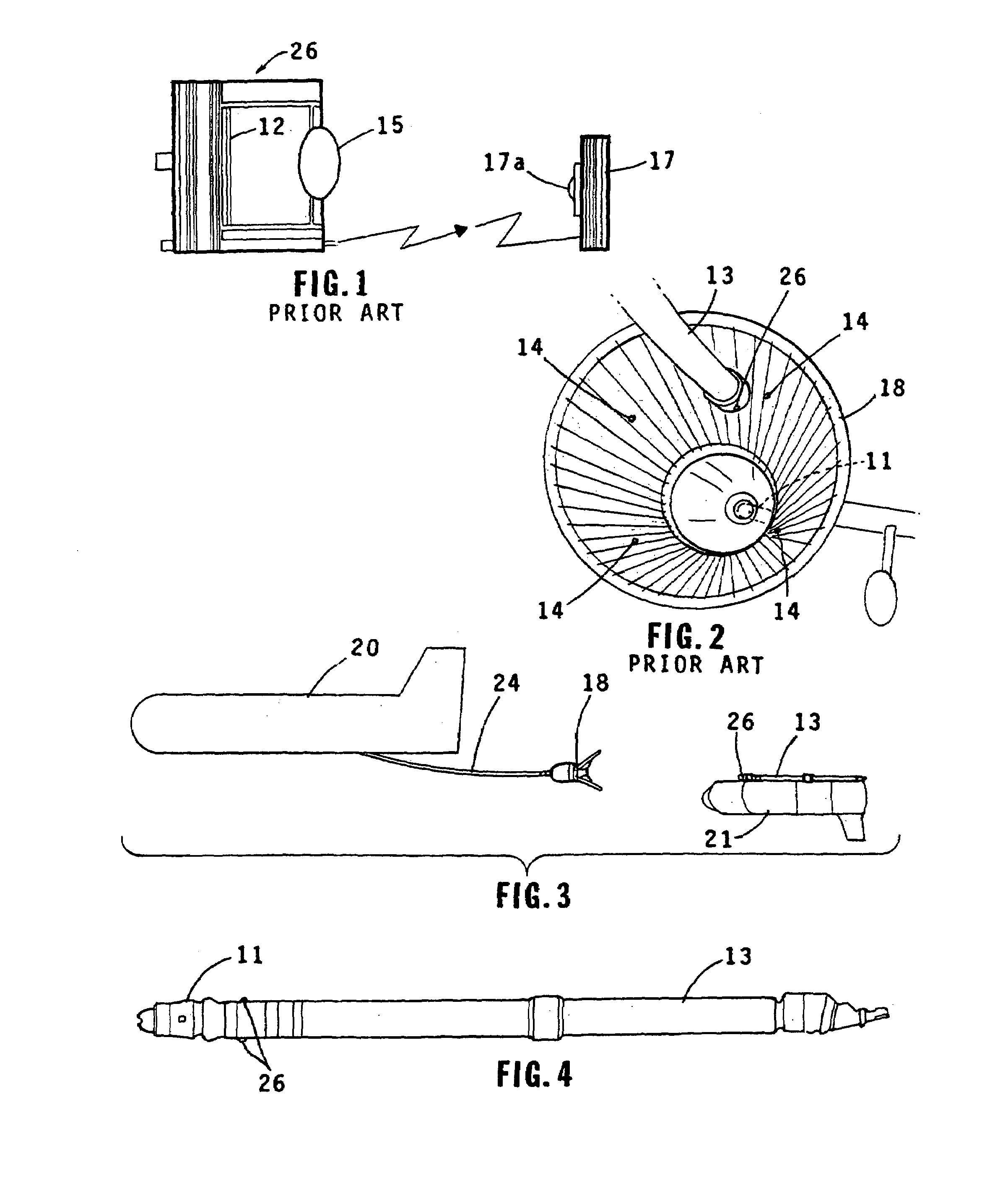
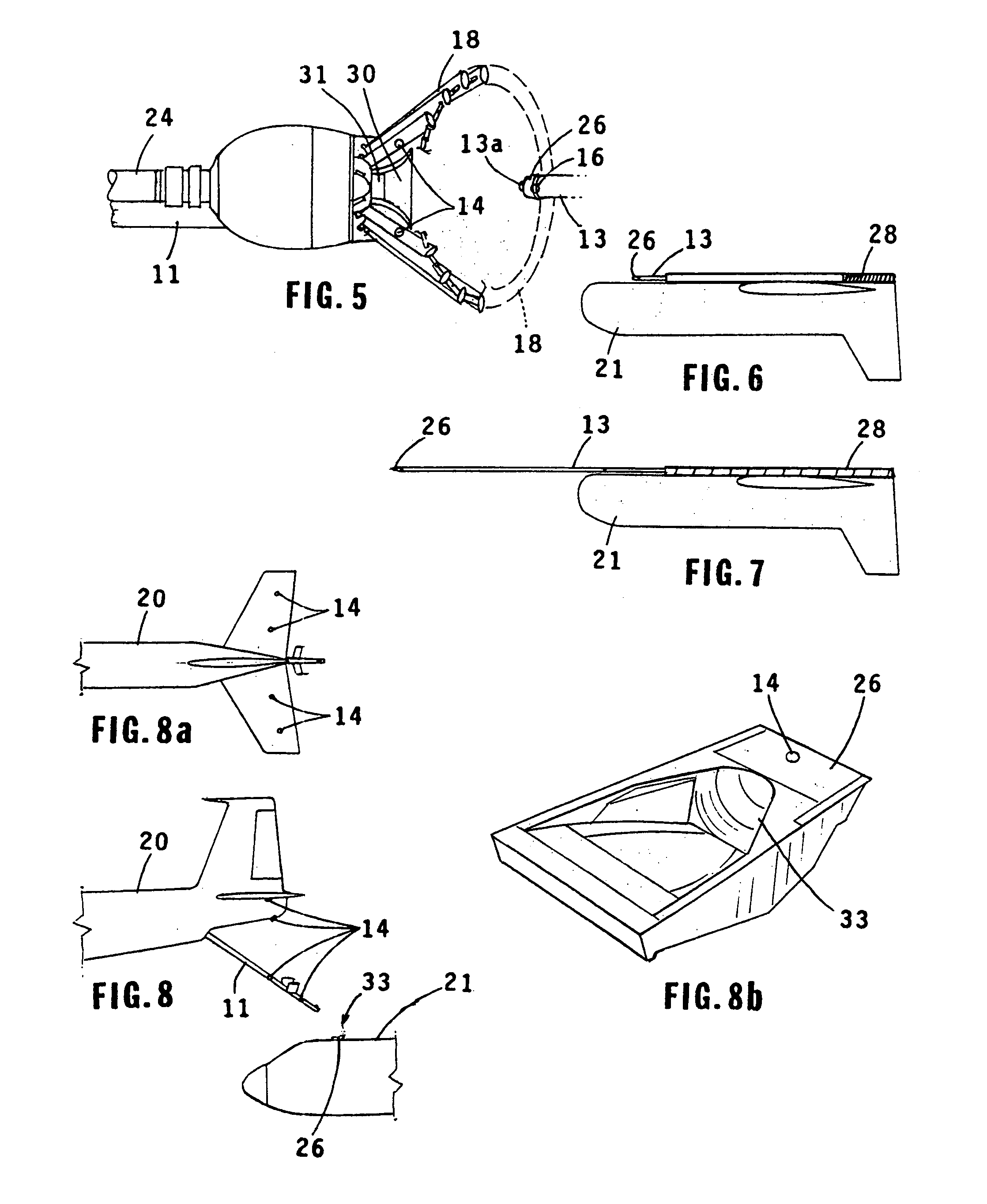
[0036]Referring now to FIGS. 3–7, the micro-probe and micro-adapter coupling of the invention for use in airborne and ground vehicles are illustrated. The micro-probe 13 is shown retracted in FIGS. 3 and 6 and in an extended position in FIG. 7. Paradrogue or “docking captive device”18 into which the micro-probe 13 is installed and which connects to the fueling hose 24 is illustrated in FIG. 5. The position and orientation errors (x, y, z, phi, theta, and psi) and their rates are determined by the VisNav measurements detected by VisNav sensors 26 on probe 13 and the navigation algorithm. These signals are used by the control system on the vehicle being refueled to drive the position and orientation errors towards zero at a rate consistent with safe operations. When these errors are near zero, the probe 13 drives spring 28 to the extended position as shown in FIG. 7 from it's at rest position as shown in FIG. 6, which in turn drives the coupling mechanism which triggers locks onto the...

second embodiment

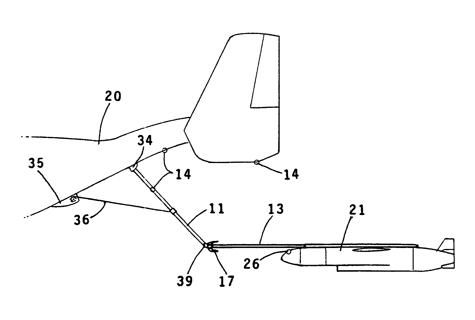
[0039]Referring now to FIGS. 8, 8A, and 8B, the invention is illustrated. The VisNav sensor 26 is positioned in the air vehicle being refueled 21 adjacent to the universal aerial refuel receptacle slipway installation (UARRSI), 33, as shown in FIG. 8. The VisNav “SmartLites”14 are mounted on the refueling vehicle on the underside of both horizontal tails, the underside of the fuselage and tail cone and the refueling boom 13. In operation, the VisNav sensor 26 mounted on the vehicle being refueled 21 detects the SmartLite transmissions and a navigation solution is calculated such that the vehicle being refueled is controlled to connect with the boom 13 and receive the transfer of fuel as in the previous embodiments. However, the beacon energy can be adjusted to optimize the centroidal accuracy of each beacon image on the detector. Pattern recognition is required to identify the measured images.

[0040]Referring now to FIGS. 9, 9A, AND 9b, a further embodiment of the invention is illust...


PUM


Abstract

A system for the hookup of either a manned or unmanned vehicle with a second vehicle which may be refueling. These vehicles may be both airborne, one airborne and the other on the ground or both on the ground. A probe extending from a first vehicle which may be refueled is joined to a paradrogue or “flycatcher” at the end of a boom on a second vehicle which may be a refueling vehicle. In bringing the probe into the paradrogue an optical sensor on one of the vehicles is employed in conjunction with optical beacons on the other vehicle with the sensor measuring the relative motion between the probe and the paradrogue and generating a control signal for controlling motion of the probe relative to the paradrogue. The positioning of the probe relative to the paradrogue is accurately controlled during the fueling operation by a reeled cable mechanism utilizing a reel which is driven to wind one end of the cable there around to retain the cable in a tensioned state. The other end of the cable is attached to the refueling vehicle . . . The cable, probe and the refueling vehicle are in a triangular configuration while allowing only small interaction forces restrains relative motion between the probe and the paradrogue.

Description

[0001]This application is based on Provisional Application No. 60 / 423,178 filed Nov. 1, 2002.BACKGROUND OF THE INVENTION[0002]1. Field of the Invention[0003]This invention relates to the hookup between multipurpose vehicles which may be either manned or unmanned and more particularly to such a hookup which may be but not necessarily for the purpose of refueling one of said air vehicles from the other.[0004]2. Description of the Related Art[0005]The capability of continuous operation of autonomous air vehicles (“UAVs”) is limited by their onboard fuel capacity. The desired capability for continuous operation 24 hours a day every day of the week of such air vehicles, which are limited by their fixed onboard fuel capacity raises a need to routinely air-refuel these vehicles. This in turn gives rise to the need for integrating a high precision navigation technology with an appropriately designed aerial refueling system which is compatible with the navigation system . . . A typical airbo...

Claims


Application Information

Patent Timeline
Patent Type & Authority Patents(United States)
IPC IPC(8): B64D39/00
CPCB64C39/024B64D39/04
Inventor GARCIA, JR., FRANKJUNKINS, JOHN L.VALASEK, JOHN L.
Owner COBHAM MISSION SYST DAVENPORT AAR INC
Why Eureka
Try Eureka