Wind deflector and open roof construction provided therewith

a technology of wind deflector and open roof, which is applied in the direction of roofs, superstructure subunits, mechanical devices, etc., can solve the problem that the lower frame part of the known wind deflector cannot be compared with the lower frame part of the present wind deflector, and achieves the effect of simple construction, cheaper and more reliabl

Active Publication Date: 2006-12-26
INALFA ROOF SYST GROUP
View PDF6 Cites 12 Cited by
  • Summary
  • Abstract
  • Description
  • Claims
  • Application Information

AI Technical Summary

Benefits of technology

[0006]When the wind deflector in accordance with the present invention has to be assembled, the lower frame part is moved towards its extended position above the level of the upper surface of the roof. As a result the lower frame part becomes very accessible such that the lower edge region of the mesh material can be attached thereto without any problem. Further, the position of the lower frame part, and thus the position of the upper frame part and mesh material extending therebetween, can be adapted to cope with different circumstances in which the wind deflector has to perform. Basically, any position of the wind deflector between the fully retracted position, a partly extended position in which the lower frame part still is positioned below said level, and a fully extended position in which both the upper frame part, mesh material and lower frame part are positioned above said level, can be chosen freely. In the first mentioned position (fully retracted) the wind deflector is not operative. In the second mentioned position (partly extended) the wind deflector basically functions as a state of the art wind deflector of the type referred to above, in which the main air flow is directed above the upper frame part with a smaller, secondary air flow through the mesh material, whereas in the third position (fully extended) also an additional air flow below the lower frame part can be generated, promoting the characteristics of the wind deflector (especially its noise-preventing characteristics).
[0009]When the wind deflector is of the pivoting type as mentioned above, preferably the first and second pivot axes coincide. That means, that only one pivot axis extending transversally is provided. This makes the mechanism of the wind deflector less complicated, cheaper and more reliable.
[0015]For increasing the effect of the wind deflector, preferably the mesh material has a main portion extending transversally with respect to the vehicle, and two sub portions at the opposite outer ends of the main portion extending substantially longitudinally with respect to the vehicle. The two sub portions contribute to the creation of a favourable flow pattern around the wind deflector and above the roof opening in the stationary roof of the vehicle.

Problems solved by technology

However, the lower frame part of this known wind deflector cannot be compared with the lower frame part of the present wind deflector, because in this state of the art wind deflector the lower edge region of the mesh material is not attached to said lower frame part, but still to a stationary roof part of the vehicle.

Method used


Image

  • Wind deflector and open roof construction provided therewith
  • Wind deflector and open roof construction provided therewith
  • Wind deflector and open roof construction provided therewith

Examples


Embodiment Construction

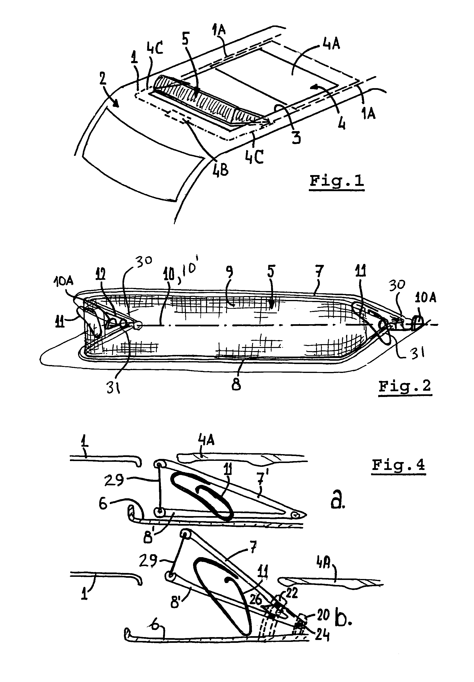
[0022]Firstly, reference is made to FIG. 1. In a stationary roof 1 of a vehicle 2 a roof opening 3 is provided which can be closed and opened by a roof assembly having a movable closure means 4 that can include, but not be limited to a panel / folding roof 4A operably connected to a drive motor or hand crank 4B via cables 4C. The panel / folding roof 4A and / or lift mechanism connected thereto can slide on stationery guide 1A. The foregoing elements are schematically illustrated since they are well known to those skilled in the art.

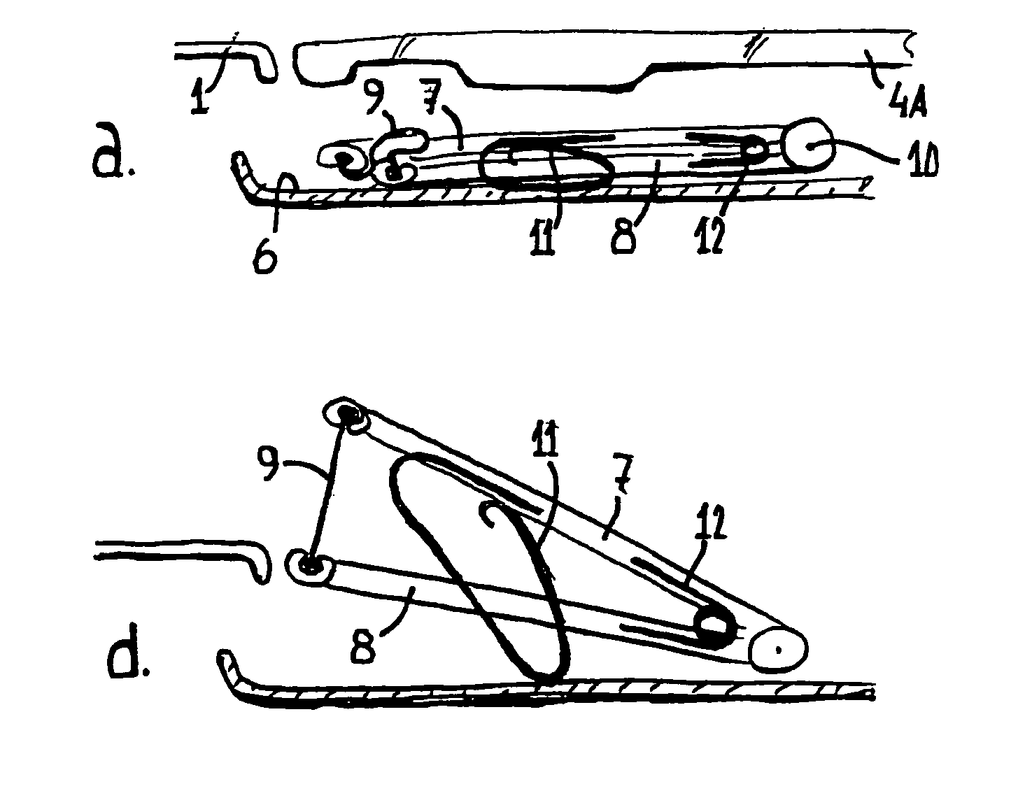
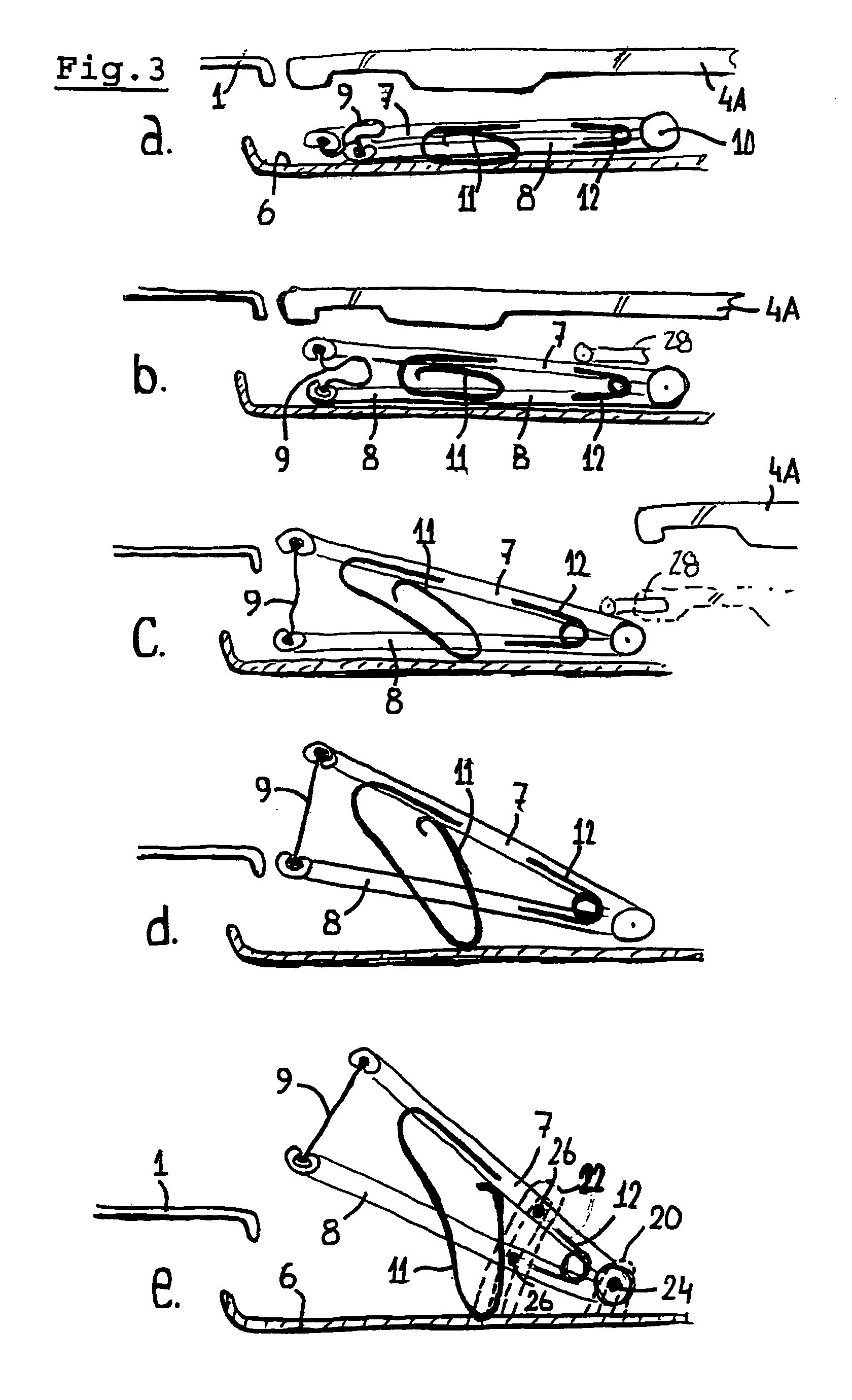
[0023]At the leading end of the roof opening 3 a wind deflector 5 is provided. The wind deflector 5 is of the type which is movable between a retracted position in which it substantially is positioned in a recess 6 (see FIGS. 3 and 4) below the level of the upper surface of the roof 1 and an extended position in which it at least partially extends above said level.

[0024]Referring to FIG. 2, the wind deflector 5 comprises a movable upper frame part 7, a lower f...


PUM


Abstract

A wind deflector is described for use at the leading end of a roof opening in the roof of a vehicle, which wind deflector is movable between a retracted position in which it substantially is positioned in a recess below the level of the upper surface of the roof and an extended position in which it at least partially extends above said level, and which wind deflector comprises a movable upper frame part, a lower frame part and a mesh material having an upper edge region attached to the upper frame part and a lower edge region attached to the lower frame part. The lower frame part together with the lower edge region of the mesh material is movable between a retracted position below said level and an extended position above said level.

Description

BACKGROUND OF THE INVENTION[0001]The invention firstly relates to a wind deflector for use at the leading end of a roof opening in the roof of a vehicle, which wind deflector is movable between a retracted position in which it substantially is positioned in a recess below the level of the upper surface of the roof and an extended position in which it at least partially extends above said level, and which wind deflector comprises a movable upper frame part, a lower frame part and a mesh material having an upper edge region attached to the upper frame part and a lower edge region attached to the lower frame part.[0002]In a known wind deflector of this type (see, for example, DE-C-10137363, EP-A-1342600 or DE-A-19518696) the lower frame part is attached to a stationary roof part of the vehicle or is defined by such a stationary roof part of the vehicle, such as a front beam of an open roof construction provided with a wind deflector. The position of such a lower frame part makes assemb...

Claims


Application Information

Patent Timeline
Patent Type & Authority Patents(United States)
IPC IPC(8): B60J7/22
CPCB60J7/22
Inventor MANDERS, PETER CHRISTIAAN LEONARDUS
Owner INALFA ROOF SYST GROUP
Why Eureka
Try Eureka