
Systems and method for forming a servo pattern on a magnetic tape

a technology of magnetic tape and servo pattern, which is applied in the direction of maintaining the alignment of the head carrier, photomechanical equipment, instruments, etc., can solve the problems of high problem of guiding tape past the tape head structure along an accurate invariant linear path

Inactive Publication Date: 2006-12-26
QUANTUM CORP
View PDF328 Cites 135 Cited by
  • Summary
  • Abstract
  • Description
  • Claims
  • Application Information

AI Technical Summary

Benefits of technology

[0008]The systems, methods and products of the invention include systems and methods for manufacturing servo tracks on a magnetic tape. In one aspect, the invention includes systems for manufacturing magnetic tapes having servo tracks thereon wherein the servo tracks are optically detectable and are capable of being processed by a servo control system for maintaining alignment of a magnetic recording head with the data tracks on the recording side of the magnetic tape. In one practice, the manufacturing sys

Problems solved by technology

Because of a relatively high linear tape velocity and because tape substrates continue to be made thinner and thinner, guiding tape past a tape head structure along an accurate invariant linear path has proven to be highly problematical.
One error phenomena is known as “lateral tape motion” or “LTM.” LTM is a major source of tracking errors in linear tape recording.

Method used


Image

  • Systems and method for forming a servo pattern on a magnetic tape
  • Systems and method for forming a servo pattern on a magnetic tape
  • Systems and method for forming a servo pattern on a magnetic tape

Examples


Embodiment Construction

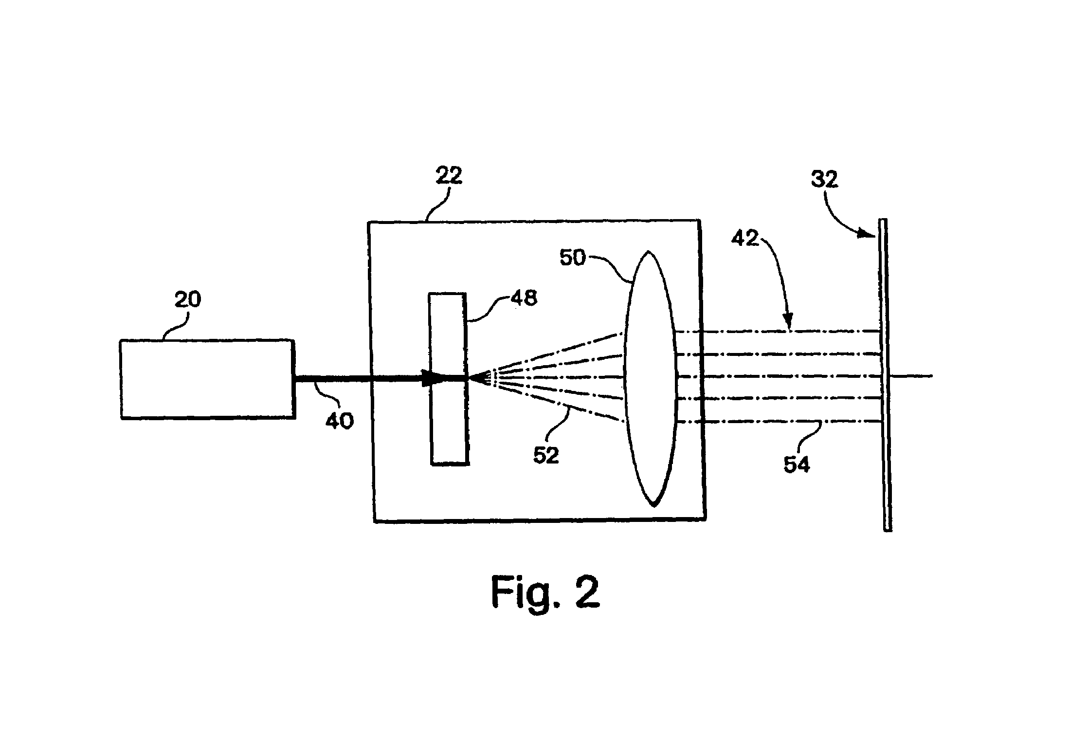
[0026]To provide an overall understanding of the invention, certain illustrative embodiments will now be described, including a system for marking a servo pattern onto a magnetic tape. In one particular illustrative embodiment, a laser is employed for engraving the non-recording surface of a magnetic tape with a plurality of servo tracks, each of which can be employed for aligning a recording head to a data track also recorded onto the magnetic tape. However, it will be understood by those of ordinary skill in the art that the manufacturing methods and systems described herein can be adapted and modified to provide alternative systems and methods each suitable for marking servo tracks onto the magnetic tape, and each deemed to be within the scope of the invention.

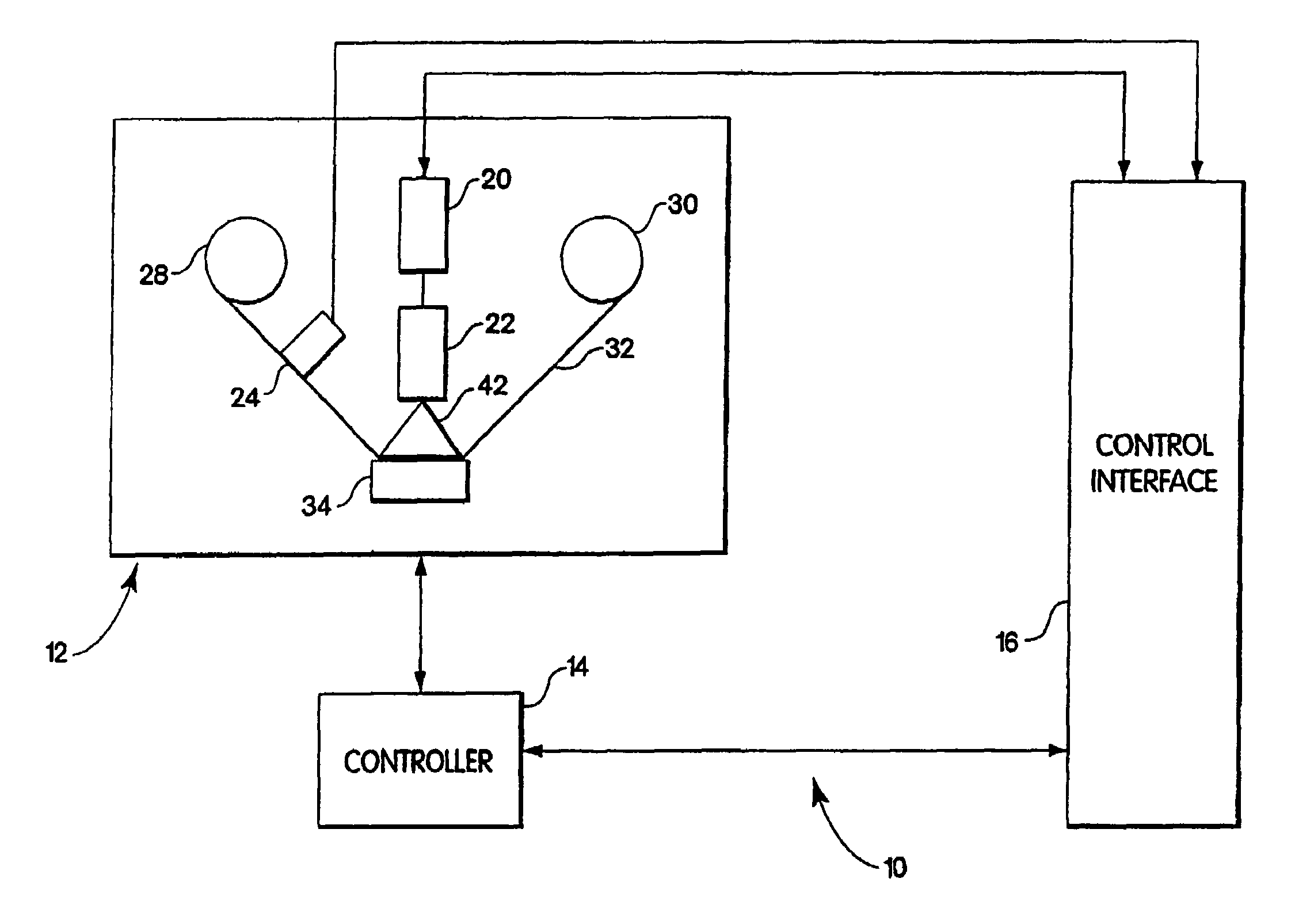
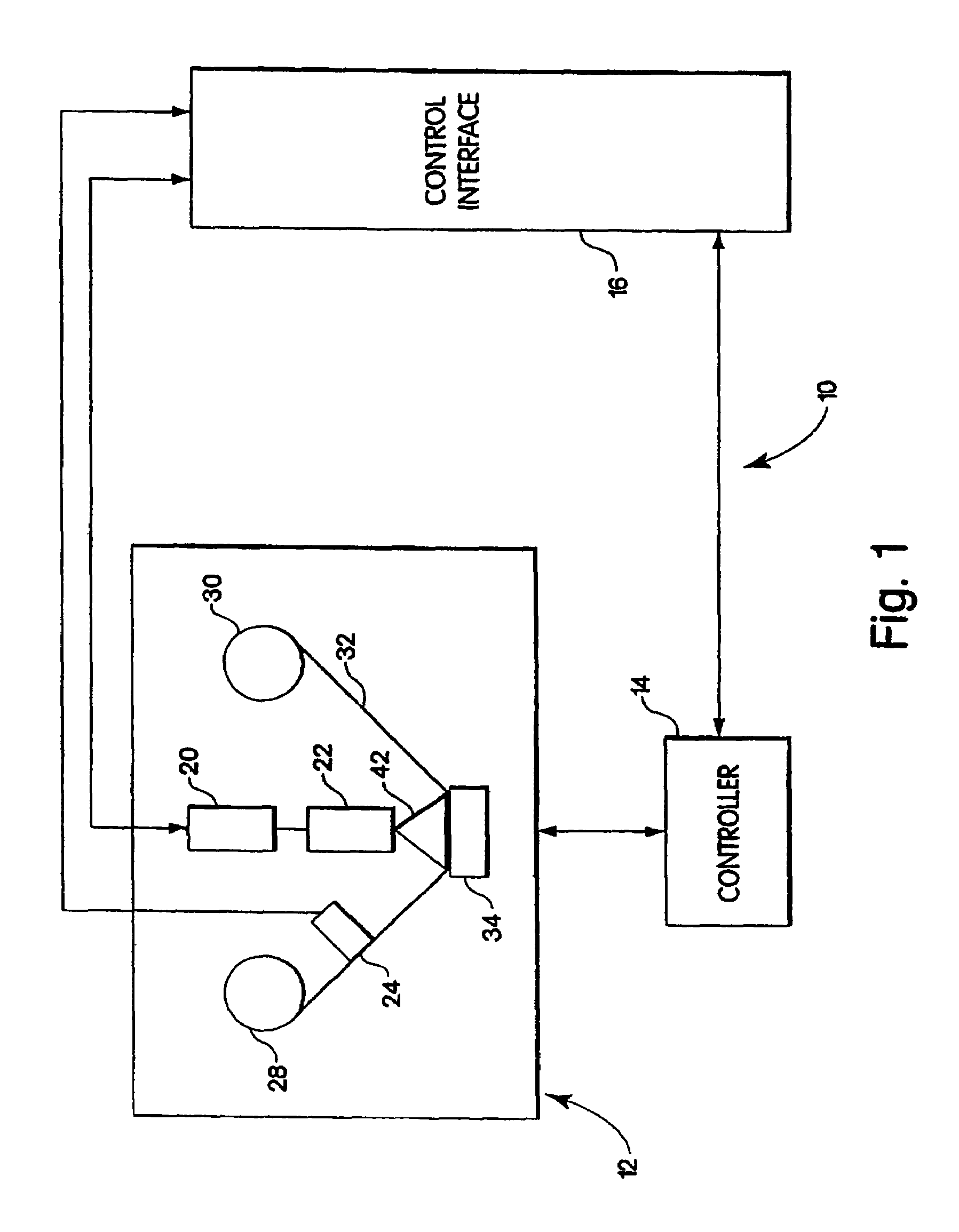
[0027]FIG. 1 shows a functional block diagram of one embodiment of a system for forming servos tracks on the magnetic tape. Specifically FIG. 1 depicts a system 10 that employs an optical engraving system to mark a servo ta...


PUM


Abstract

The systems, methods and products of the invention include systems and methods for manufacturing servo tracks on a magnetic tape. In one aspect, the invention includes systems for manufacturing magnetic tapes having servo tracks thereon wherein the servo tracks are optically detectable and are capable of being processed by a servo control system for maintaining alignment of a magnetic recording head with the data tracks on the recording side of the magnetic tape. In one practice, the manufacturing systems described herein engrave the servo tracks onto the non-recording side of a magnetic tape by directing a laser beam at the non- recording side of the magnetic tape. In another practice, the manufacturing systems described herein engrave the servo tracks onto the magnetic side of a magnetic tape by directing a laser beam at the magnetic side of the magnetic tape. Such engraved patterns can act as optical servo tracks for maintaining alignment of the recording head with the data tracks on the magnetic tape.

Description

REFERENCE TO RELATED APPLICATIONS[0001]This application is a divisional of Ser. No. 09 / 361,669, filed Jul. 27, 1999, which is a CIP of earlier filed U.S. patent application Ser. No. 09 / 046,723, entitled “Multi-Channel Magnetic Tape System Having Optical Tracking Servo”, filed 24 Mar. 1998, now abandoned and naming Joseph Panish as an inventor, the disclosure of which is incorporated by reference.FIELD OF THE INVENTION[0002]The invention relates to systems and methods for manufacturing recording tape, and more specifically, to systems and methods for formatting a recording tape with servo tracks.BACKGROUND OF THE INVENTION[0003]Digital tape recording remains a viable solution for storage of massive amounts of data. Conventionally, at least two approaches are employed for recording digital information onto magnetic recording tape. One approach calls for moving the tape past a rotating head structure which records and plays back user information from discontinuous transverse tracks. In...

Claims


Application Information

Patent Timeline
IPC IPC(8): B05B5/025G11B5/584
CPCG11B5/584
Inventor CHEN, HONGPANISH, JOSEPH M.LEE, TZUO-CHANGCAPPABIANCA, LEO
Owner QUANTUM CORP
Learn More