Method of making porous ceramic matrix composites

a technology of porous ceramics and composites, applied in the field of ceramic structures, can solve the problems of high thermally induced stress in the component, low thermal conductivity, and a large number of holes, and achieve the effect of increasing cooling flow capabilities

Active Publication Date: 2006-12-26
GENERAL ELECTRIC CO
View PDF26 Cites 40 Cited by
  • Summary
  • Abstract
  • Description
  • Claims
  • Application Information

AI Technical Summary

Benefits of technology

[0009]Another object of this invention is increased cooling flow capabilities for a ceramic structure having holes and channels yielding greater than 5 times the flow than for the same ceramic structure without holes and channels.

Problems solved by technology

However, the low thermal conductivity poses a serious problem for use of CMC's in high temperature applications involving very rapid heat-up, such as the flowpath of a gas turbine engine.
In applications such as turbine engines, the low thermal conductivity of CMCs causes high thermally-induced stresses in the component.
This usually requires thousands of holes even for relatively small parts.
While both of these processes work well, both are time consuming and expensive, especially for complex-shaped components.

Method used


Image

  • Method of making porous ceramic matrix composites
  • Method of making porous ceramic matrix composites
  • Method of making porous ceramic matrix composites

Examples


example 1

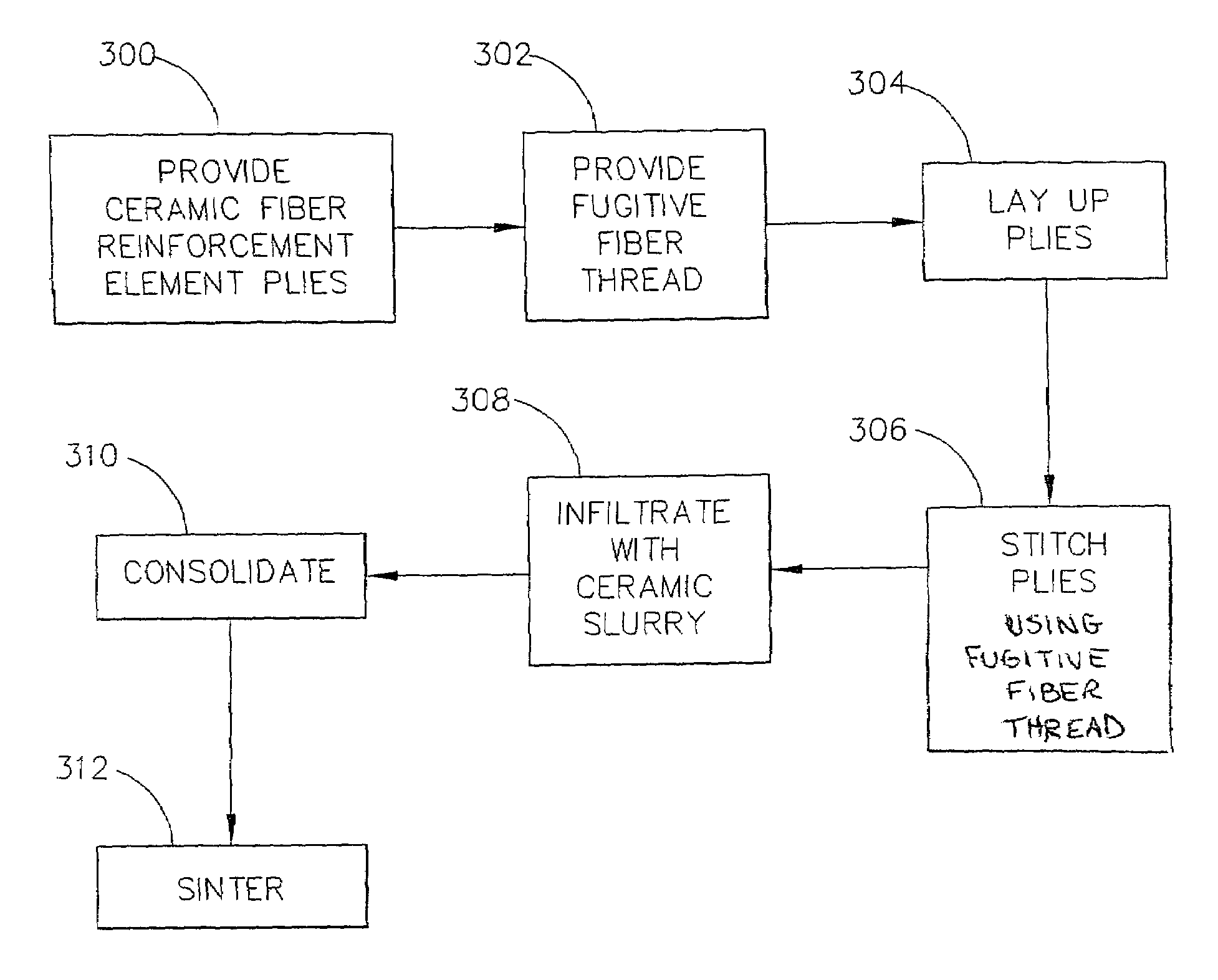
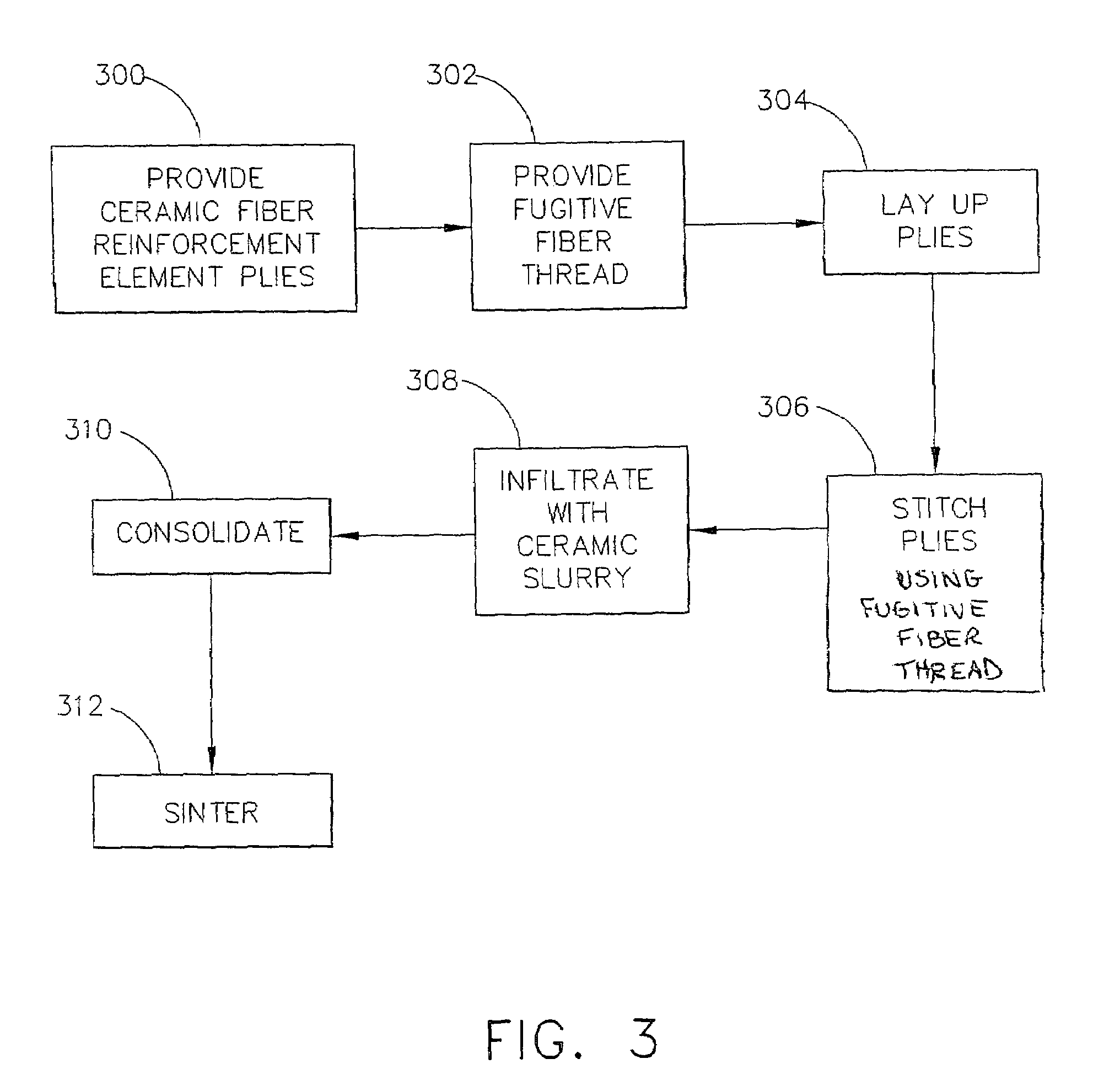
[0033]In Example 1, evaluated in connection with the present invention, a Nextel® 440 ceramic cloth was cut into 4-in square plies. Nextel® 440 is made from Al2O3, SiO2, and B2O3 at varying percentages, and has both crystalline and glassy phases—the glassy phase helps the fiber retain strength after exposure to high temperature, but also weakens the fiber when stressed at high temperature. is a registered trademark for ceramic textiles, and is owned by 3M Corporation, St. Paul, Minn., USA. On one ply, lines were inked on the surface about 0.75 cm apart from each other either along the warp direction of the ceramic cloth ply (1D) or in both the warp and fill directions (2D). Four plies were stacked together with the top ply being the one with the inked pattern. The stacked plies were stitched along the inked pattern with a #61 rayon thread on a ConSew® Premier Model No. CN3115RB sewing machine at a 2.5, 3.5 and 4.5 setting. Consew® is a registered trademark of Consolidated Sewing Mac...

example 2

[0034]In Example 2, a Nextel®440 ceramic cloth was prepregged with silica powder, SiO2-yielding polymer slurry previously described in Example 1. The prepregged cloth was cut into 4 inch square plies, and 4 of these plies were stacked together as well as 2 sets of 2-ply thick laminates. A 1D patterned lines 0.75-cm apart were inked onto a 4-in square sheet of plastic. Additionally, a 2D pattern with lines 0.75-cm apart were inked onto 2,4-in square plastic sheets. A 1D patterned plastic sheet was placed on top of the 4-ply thick stack while the 2D patterned plastic sheets were placed on both of the 2-ply thick stacks. The stacked prepreg lay-ups were stitched along the inked pattern with a #61 rayon thread on a ConSew sewing machine with a machine setting of 3.5. The two 2-ply stitched lay-ups were offset from each other about 0.37 cm in both the warp and fill cloth directions, stacked and lightly pressed together to stabilize the offset. The stitched prepregged stacks were bagged a...


PUM

PropertyMeasurementUnit
temperatureaaaaaaaaaa
pressureaaaaaaaaaa
temperatureaaaaaaaaaa

Abstract

A ceramic matrix composite (CMC) structure, and method of forming same, the structure having internal air flow channels and cooling holes created by the process of sewing or stitching a fugitive fiber or thread into plies of ceramic cloth, preferably prior to consolidation of the ceramic cloth with a CMC slurry, followed by heating to convert the slurry material to a hardened ceramic component part of a predetermined shape. Upon heating the infiltrated and consolidated ceramic cloth to about between 1100 and 2100 degrees Fahrenheit, such as by hot pressing the structure containing the fugitive fibers therein, the fugitive fibers disintegrate, leaving channels and cooling holes wherever the stitched fugitive fiber or thread was previously located. Thus, the channels and cooling holes flow between plies as well as across the surface of the top and bottom plies.

Description

FIELD OF THE INVENTION[0001]The present invention is directed to ceramic structures with holes and internal channels for cooling these structures, and to methods for making the holes and channels within and through the ceramic structures using stitched fugitive fibers in ceramic cloth to produce the holes and channels.BACKGROUND OF THE INVENTION[0002]Ceramic matrix composites (CMCs) have relatively low thermal conductivities and are thus well suited for use in high temperature environments for long periods of time. However, the low thermal conductivity poses a serious problem for use of CMC's in high temperature applications involving very rapid heat-up, such as the flowpath of a gas turbine engine. In applications such as turbine engines, the low thermal conductivity of CMCs causes high thermally-induced stresses in the component. Mathematically simplified, this relationship is represented by the equation σ=E α / K; where σ is the thermally-induced stress, E is the elastic modulus, α...

Claims


Application Information

Patent Timeline
Patent Type & Authority Patents(United States)
IPC IPC(8): B29C33/76B32B3/00B32B3/10C04B35/14C04B35/80C04B38/06
CPCC04B35/14C04B35/803C04B35/82C04B38/065C04B35/6264C04B35/18C04B38/067C04B38/0675Y10T428/24273C04B2235/3418C04B2235/48C04B2235/5212C04B2235/5228C04B2235/5268C04B2235/5445C04B35/80C04B2235/5252
Inventor MILLARD, MICHAEL LEERICHARDSON, JR., HORACE
Owner GENERAL ELECTRIC CO
Why Eureka
Try Eureka