Terminal and method for remotely controlling device using the same

a technology of remote control and terminal, which is applied in the direction of two-way working systems, instruments, television systems, etc., can solve the problems of difficult to adjust the position of the terminal, etc., to achieve the effect of convenient addition and replacement of the appliance and superior operation

Inactive Publication Date: 2006-12-26
SONY CORP
View PDF9 Cites 31 Cited by
  • Summary
  • Abstract
  • Description
  • Claims
  • Application Information

AI Technical Summary

Benefits of technology

[0007]Accordingly, it is an object of the present invention to provide a terminal which has superior feel of operation and which easily accommodates the addition and replacement of an appliance to be controlled, as well as a remote control method using the same.

Problems solved by technology

However, even for a notebook computer, a personal computer designed with serious consideration on portability, the operations of a keyboard, a mouse, and the like are required.
This therefore does not allow everyone to remotely control the appliance easily from the beginning.
In addition, since the portable information terminal is principally operated using a pen or a button, it takes a certain amount of time for the user to intuitively operate it.
Furthermore, when an appliance is replaced or a feature is changed, complicated replacing processes should not be required on the terminal side.

Method used


Image

  • Terminal and method for remotely controlling device using the same
  • Terminal and method for remotely controlling device using the same
  • Terminal and method for remotely controlling device using the same

Examples


Embodiment Construction

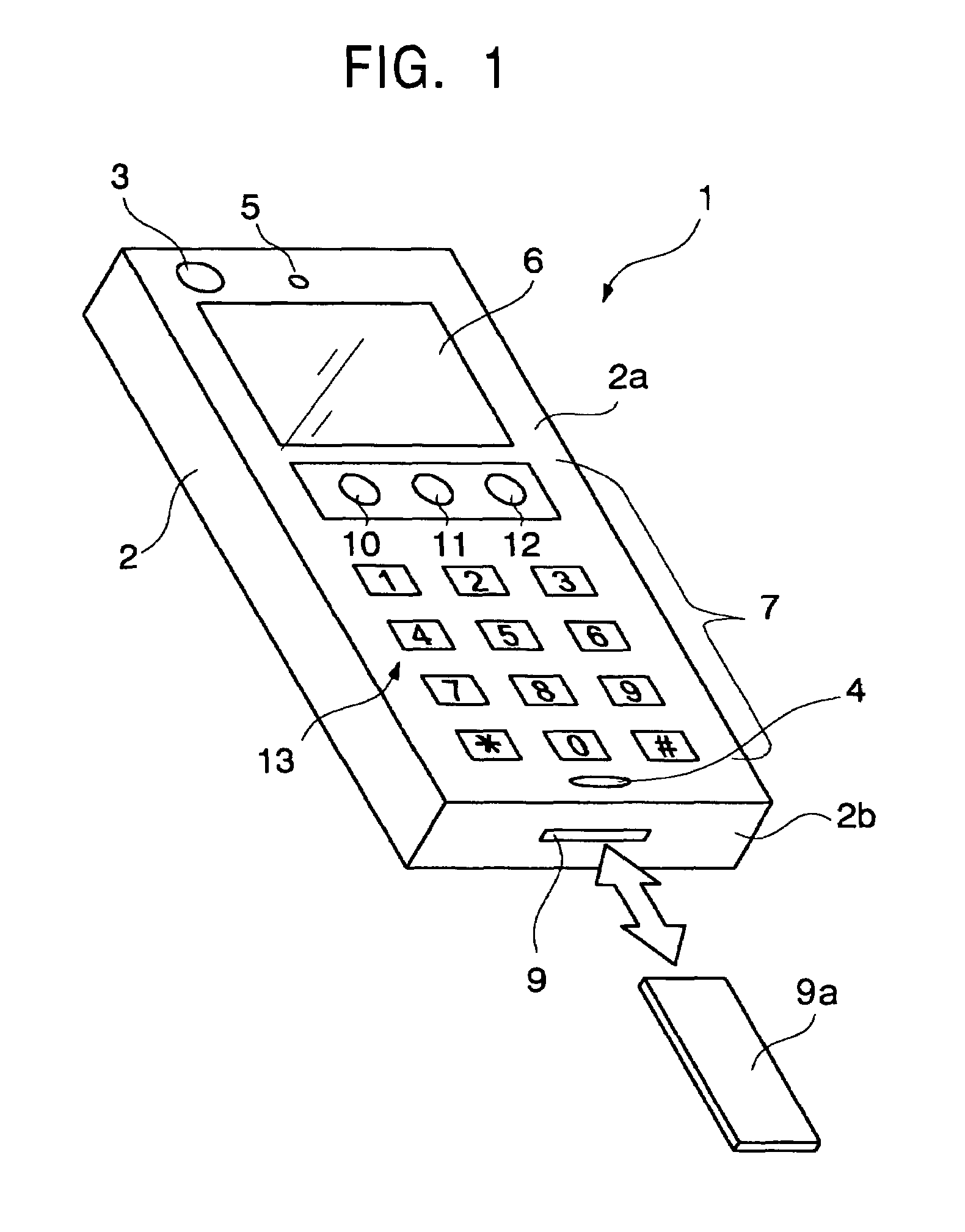
[0026]FIG. 1 shows a perspective view of a general outline of a terminal 1 having the ability to remotely control an appliance according to a first embodiment of the present invention.

[0027]As shown in FIG. 1, the terminal 1 has a casing 2 that may be carried single-handed, for example. On a front face 2a of the casing 2 may be provided a camera 3, a microphone 4, a loudspeaker 5, a display unit 6, an operation region 7, and an infrared communication transmitting and receiving unit (not shown). On a bottom face 2b of the casing 2 may be provided a load unit 9 in which a stick-type storage media 9a can be loaded in a removable manner. The camera 3 may include a CCD (Charge-Coupled Device) camera, and the display unit 6 may include a color LCD (Liquid Crystal Display). The operation region 7 includes an OK button 10, an Undo button 11, a picture-taking button 12, and a numeric-key set 13.

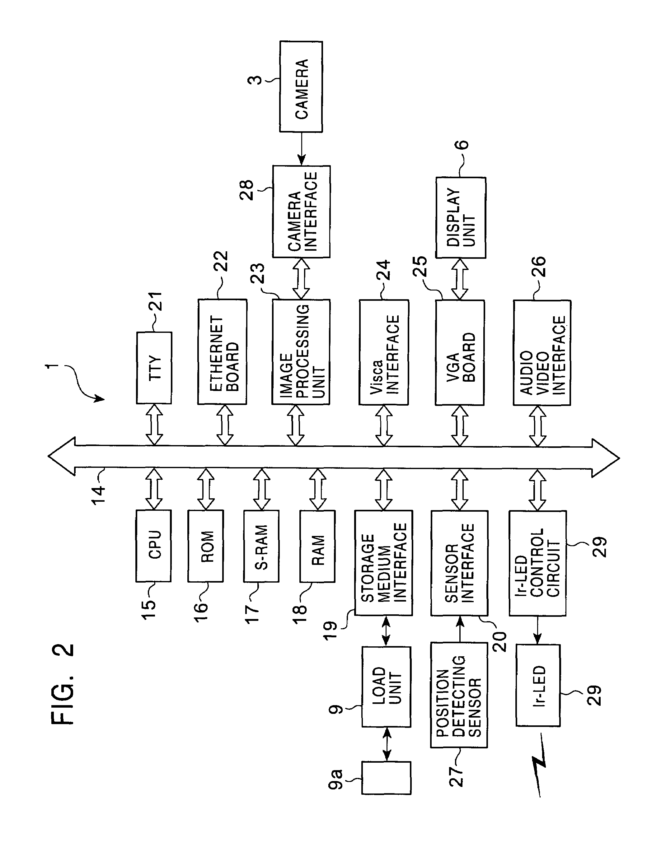
[0028]FIG. 2 shows the hardware configuration of the terminal 1.

[0029]As shown in FIG. 2, the term...


PUM


Abstract

Device names and device control parameters are registered in a content table of a terminal. These device names and control parameters are each associated in the content table with partial images forming a total image. A user causes an arbitrary partial image to be displayed on a display screen of the terminal by moving the position of the total image relative to the display screen. After reading the device name and the control parameters corresponding to the arbitrary partial image from the content table, the terminal remotely controls the targeted terminal based on the information read. Therefore, the targeted device and the control description thereof can be selected using a simple operation, such as moving the position of the image to be displayed on the display screen. The addition or replacement of targeted devices can be easily accommodated by updating the content table.

Description

CROSS-REFERENCE TO RELATED APPLICATIONS[0001]The present application claims priority from Japanese Application No. 2002-114031 filed Apr. 16, 2002, the disclosure of which is hereby incorporated by reference herein.BACKGROUND OF THE INVENTION[0002]The present invention relates to terminals for remotely controlling devices including home electric appliances, and more particularly relates to a terminal for permitting the replacement of remote control devices and relates to a method for remotely controlling the devices using the same.[0003]Recently there have been proposed systems, called a home network, in which not only personal computers but also other various types of home electric appliances link to the Internet or LANs to permit them to be remotely controlled. The home electric appliances that are compatible with the home network are not only audio-visual appliances, such as televisions and video recorders, but also refrigerators, microwaves, and so on, and they are expected to i...

Claims


Application Information

Patent Timeline
Patent Type & Authority Patents(United States)
IPC IPC(8): G09G5/00G05B23/02G06F1/16G06F13/00G06F17/30G06Q10/00G06Q30/04G06Q30/06G06Q50/00H04N5/445H04N7/24H04N21/41H04N21/433H04N21/436H04Q9/00
CPCG06F1/1626G06F1/1656G06F1/1686G06F1/1694G06F17/30864H04N5/44582H04N21/4108H04N21/4131H04N21/4332H04N21/43615G06F2200/1637G06F16/951H04N21/42204H04N21/47
Inventor USUDA, HIROSHI
Owner SONY CORP
Why Eureka
Try Eureka