Configuration method for an installation comprising solar protection and/or lighting devices

Active Publication Date: 2006-12-26
SOMFY ACTIVITES SA
15 Cites 48 Cited by

AI-Extracted Technical Summary

Problems solved by technology

Two equipments whose operation is similar will also have to be subjected to specific programming, which makes the configuration and the programming tedious.
However, in the case of the patent application EP 1 054 134, the funct...

Benefits of technology

[0009]The purpose of the invention is to propose a configuration method improving the methods known in the prior art and overcoming the aforesaid disadvantages. In particular,...

Abstract

The configuration method for an installation comprising solar protection and/or lighting devices controlled by a central unit comprising a memory, microprocessor and a user interface, is characterized in that method comprises an iteration, over all of the solar protection and/or lighting devices, and comprises a parameterization step that includes phases of entry and recording of data defining the exposure of the opening fitted with the solar protection device with respect to the sun, entry and recording of data defining the type of device, and entry and recording of data defining the maximum desired depth of penetration of the sun into the building, and/or the sought visual comfort. The method further comprises a calculation step whereby for each device, coefficients for a control algorithm and/or a control algorithm, intended to control the device, are calculated.

Application Domain

Technology Topic

Image

  • Configuration method for an installation comprising solar protection and/or lighting devices
  • Configuration method for an installation comprising solar protection and/or lighting devices
  • Configuration method for an installation comprising solar protection and/or lighting devices

Examples

  • Experimental program(1)

Example

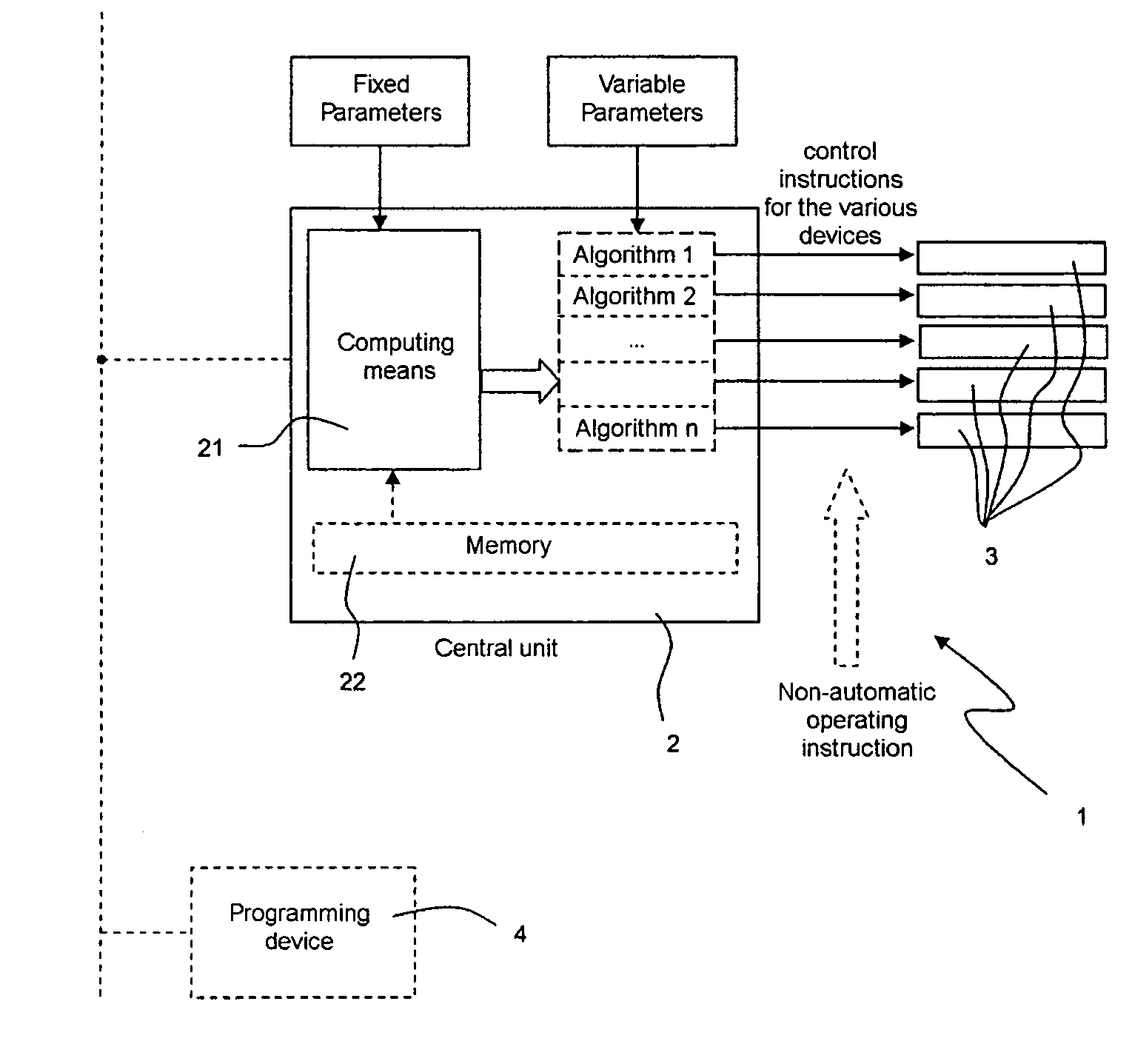
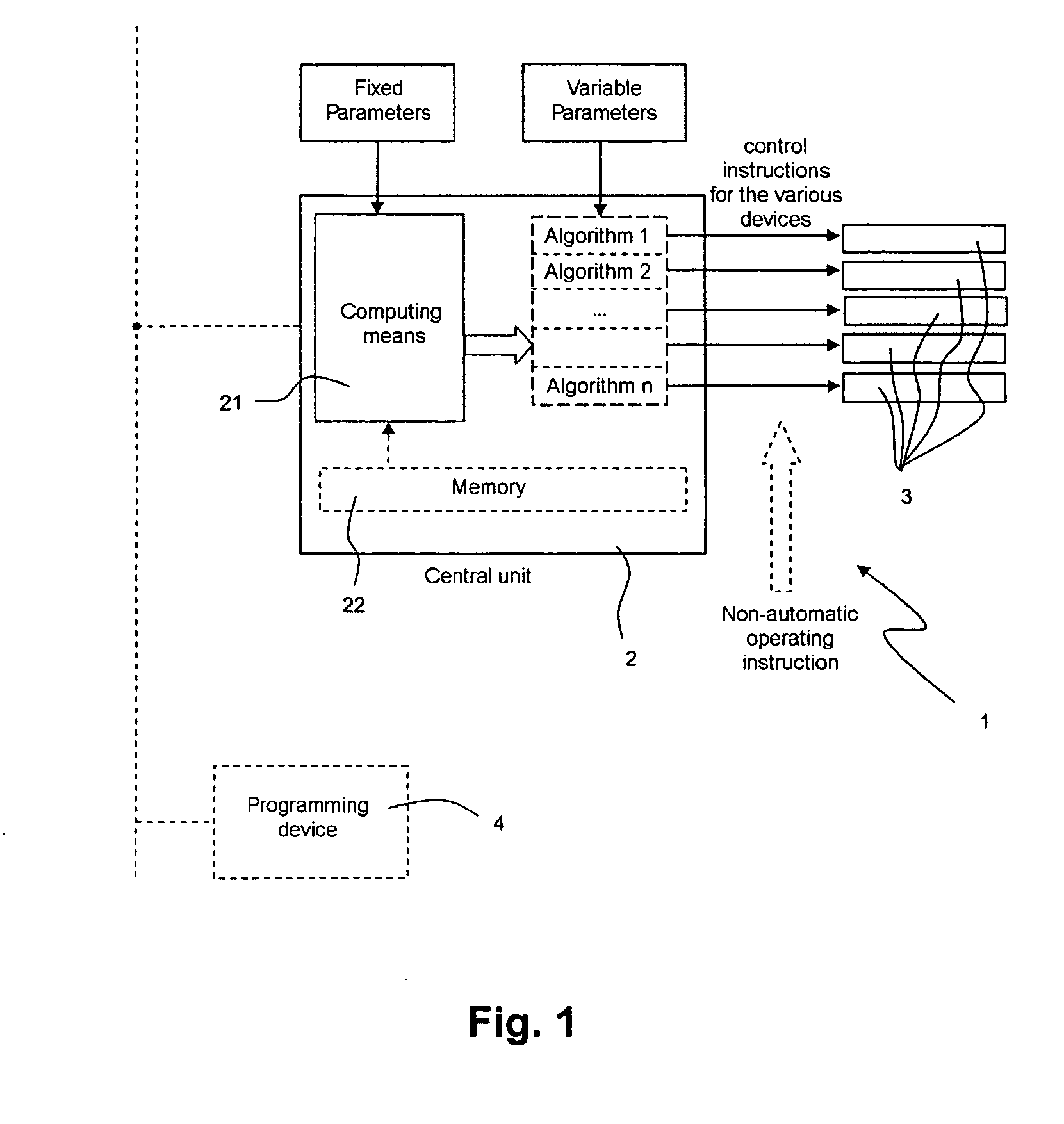
[0050]The installation shown in FIG. 1 comprises a central control unit 2 controlling motorized solar protection devices 3 equipping the openings of a building. They could also be lighting devices for rooms of the building provided with such openings. The central unit can be connected by a bus line, possibly in a network with other similar central control units.
[0051]The central control unit 2 can be configured directly or by the intermediary of a programming device 4, such as a computer. In the first case, the control system has a screen and an interface of the keyboard type upon which the data necessary for the operation of the installation is entered.
[0052]The central control unit 2 comprises computing means 21 such as a microprocessor and possibly a memory 22.
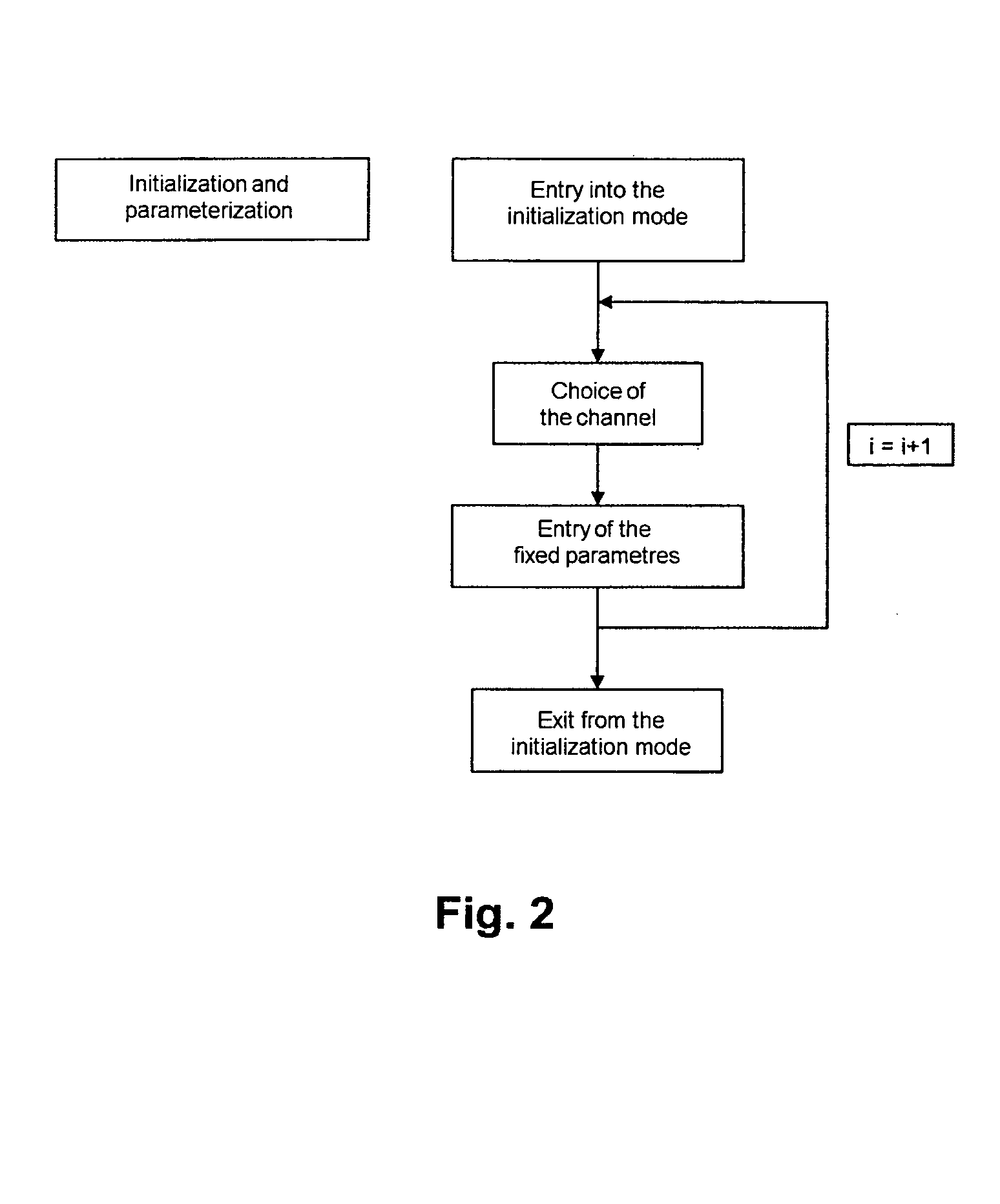
[0053]The installation receives on the one hand fixed parameters, during an initialization phase. These fixed parameters are of immutable nature, at least until modification of the characteristics of the solar protection and/or lighting devices during a renovation of the building. They consist, for example, of information defining the exposure of each opening of the building provided with a solar protection device and the different types of solar protection devices used in the building. This information is recorded in memory.
[0054]On the other hand, the installation receives variable parameters, after the initialization phase. These variable parameters consist of information on time, supplied by a clock, and of meteorological data on wind, temperature and illumination coming from various sensors and making it possible to define the internal and external environments of the building varying over the course of time.
[0055]The memory contains information relating, on the one hand, to the technical operational characteristics of the motorized solar protection and/or lighting devices of different types and, on the other hand, general information, such as for example the determination of the movement of the sun over the course of the year, the management of energy in the building and the management of the occupation of the building. All or some of this information can be stored in the memory before the installation of the central control unit in the building, for example by the manufacturer of the said central control unit.
[0056]It is also possible for this memory to form part of the independent programming device 4. It can then also be common with a control installation assembly.
[0057]The information contained in the memory is used by the computing means in order to provide, as a function of the fixed parameters entered in the memory of the installation, specific operational algorithms for each controlled device, or at least specific coefficients for each controlled device that are usable by a same algorithm.
[0058]By way of example, the index “i” denotes one of the solar protection and/or lighting devices.
[0059]The following fixed parameters are entered and recorded during the parameterization phase:
[0060]Fi: parameters relating to the exposure of the opening provided with the device, if the device is a solar protection device,
[0061]D1i: parameters relating to the device,
[0062]Li: parameters related to a choice of visual comfort in the zone covered by the device. The following information is read from memory:
[0063]D2i: other parameters relating to the device.
[0064]It is assumed that the variable parameters are time T and external sunshine, measured by the frontal illumination E.
[0065]In a first case, the central unit comprises computing means which will generate as many algorithms Ai as there are different products or products subjected to different conditions: thus the control law of a device is expressed by Ai(T, E), in which the algorithm Ai is itself dependent on Fi, D1i, D2i, Li.
[0066]In a second case, the central unit comprises computing means which will generate as many groups of coefficients Ci as there are different products or products subjected to different conditions. These coefficients are used by a same algorithm: thus the control law of a device is expressed by Ai(Ci, T, E) in which the coefficients Ci are dependent on Fi, D1i, D2i, Li.
[0067]The central unit also manages the interactions between the solar protection and/or lighting devices: thus the algorithms specific to each device take account of this management.
[0068]The control instructions of the solar protection and/or lighting devices are then generated on the basis of the algorithms and/or operational instruction values and variable parameters.
[0069]A non-automatic instruction to operate a solar protection device can possibly replace or temporarily invalidate the instructions provided by the central unit.
[0070]In a first phase, referred to as the parameterization phase, diagrammatically represented in FIG. 2, the user or the installer enters the fixed parameters specific to each controlled solar protection and/or lighting device. He must then enter the initialization mode. Then, he must select a control output and enter fixed parameter values corresponding to the solar protection device controlled by that output. These parameters are stored in the memory of the installation. These steps must be iterated on all of the outputs controlling a device. It is not obligatory for all of the control outputs of the central unit to be connected to a device. These fixed parameters consist, for example and as seen previously, of values defining the exposure of the opening equipped by the device and of a value defining the type of solar protection. The fixed parameters defining the type of solar protection and/or lighting device can be stored in memory automatically, for example during an initial communication between the central unit and each of the controlled devices.
[0071]In a second phase, referred to as the initialization and computing phase, diagrammatically represented in FIG. 3, the computing means 21 use both the fixed parameters stored in memory and the general information, which is also stored in memory, in order to determine operational algorithms for the solar protection devices, and/or coefficients for such an algorithm. The user must cause the entry into a computing mode. He must select a control output of the central unit. The computing means then read the fixed parameters relating to the solar protection device controlled by the chosen control output. The computing means then use the general information stored in memory in combination with the fixed parameters in order to produce an operational algorithm, and/or coefficients for an operational algorithm of the device connected to the selected control output. These different steps are also iterated automatically on all of the outputs of the central unit controlling a solar protection device. Once the algorithms are established independently for each device, the central unit checks that the operations induced by these algorithms do not risk generating contradictions. If such is the case, it modifies the corresponding algorithms in order to manage the conflicts and the interactions.
[0072]Once this phase is completed, the installation is configured and operational.
[0073]Periodically and automatically, the installation switches into the operational mode shown in FIG. 4. The variable parameters coming from different sensors and a clock are read and integrated in the operational algorithms in order to generate control instructions governing the operation of the solar protection and/or lighting devices. A control output is selected automatically, the variable parameters are integrated in an operational algorithm in order to generate a control instruction for the solar protection and/or lighting device controlled by the selected control output, then the instruction is sent to the device. These steps are iterated on all of the outputs controlling a solar protection and/or lighting device.

PUM

no PUM

Description & Claims & Application Information

We can also present the details of the Description, Claims and Application information to help users get a comprehensive understanding of the technical details of the patent, such as background art, summary of invention, brief description of drawings, description of embodiments, and other original content. On the other hand, users can also determine the specific scope of protection of the technology through the list of claims; as well as understand the changes in the life cycle of the technology with the presentation of the patent timeline. Login to view more.

Similar technology patents

Classification and recommendation of technical efficacy words

  • Reduce amount of data
  • Simple method

Detecting irises and pupils in images of humans

ActiveUS20060098867A1Good efficient and moderate computing resourceSimple methodImage enhancementImage analysisEye detectionPupil
Owner:MONUMENT PEAK VENTURES LLC
Why Eureka
Try Eureka