Anti-wicking protective workwear and methods of making and using same

a workwear and anti-wicking technology, applied in the field of protective workwear, can solve the problems of garments often being uncomfortable to wear, materials being uncomfortable to wear, garments often being uncomfortable, etc., and achieve the effect of low surface tension and low surface tension

Inactive Publication Date: 2007-01-02
O&M HALYARD INC
View PDF313 Cites 27 Cited by
  • Summary
  • Abstract
  • Description
  • Claims
  • Application Information

AI Technical Summary

Benefits of technology

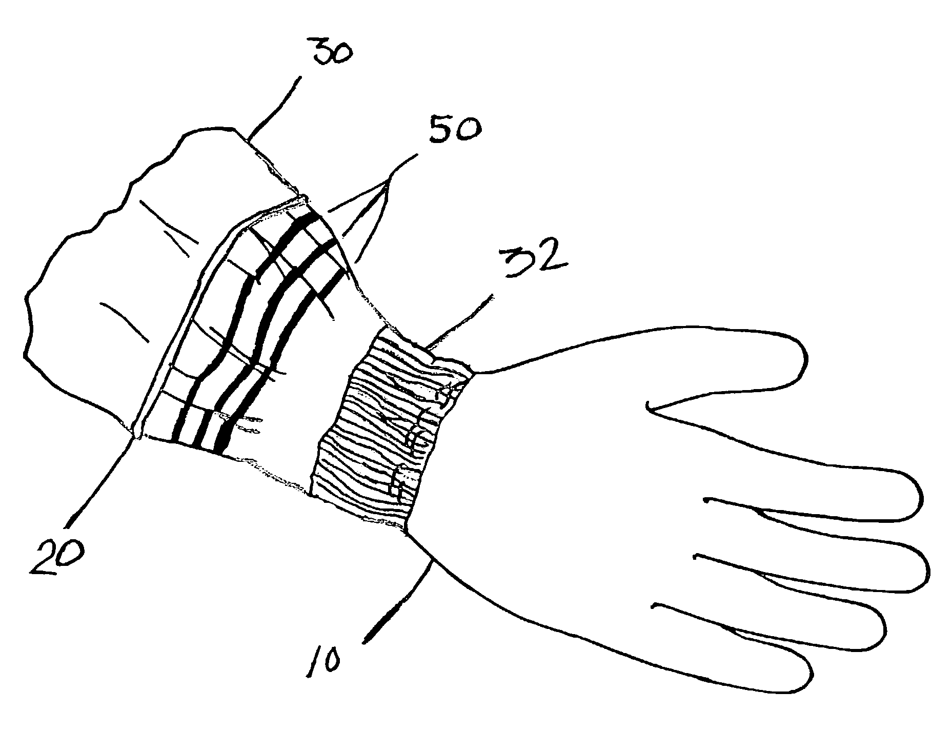
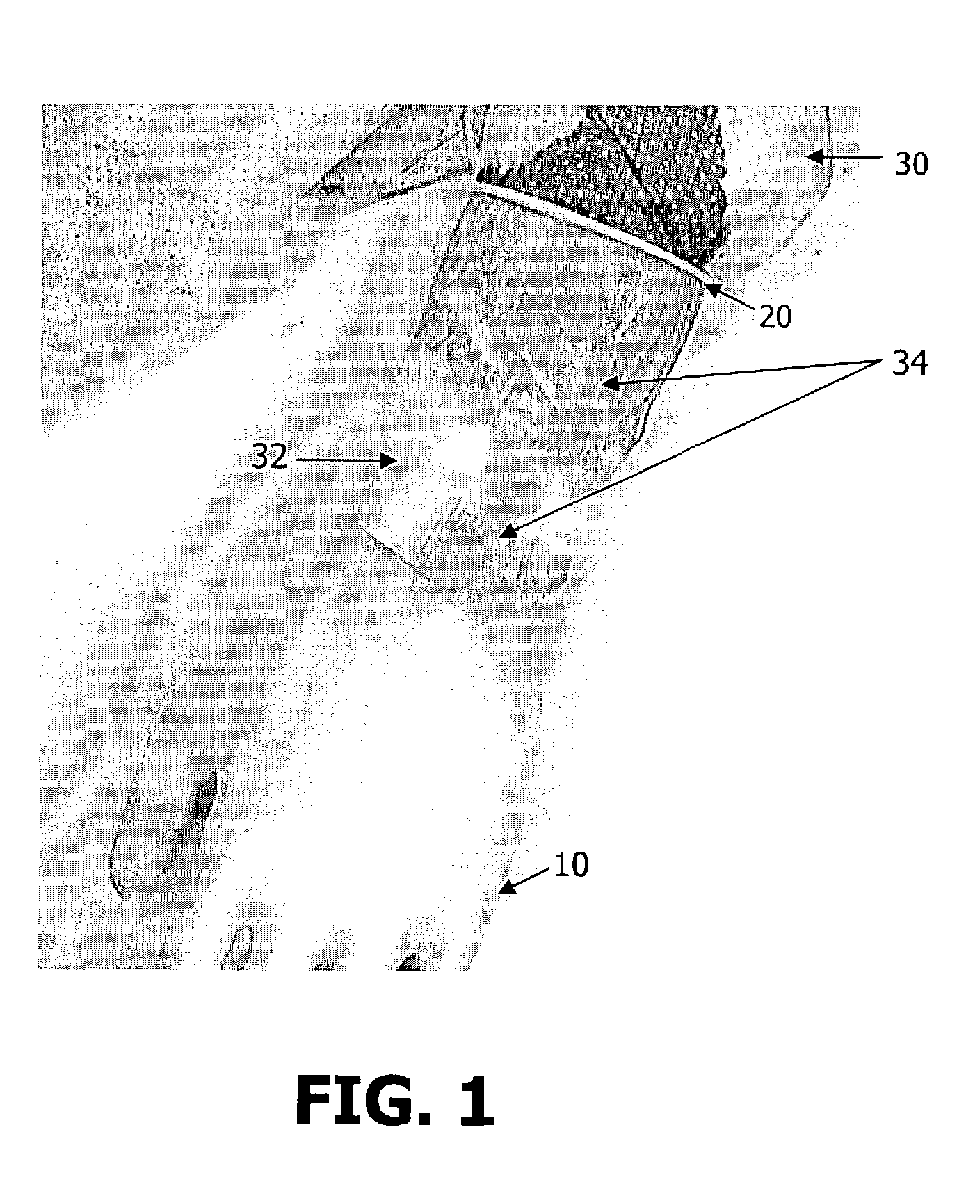
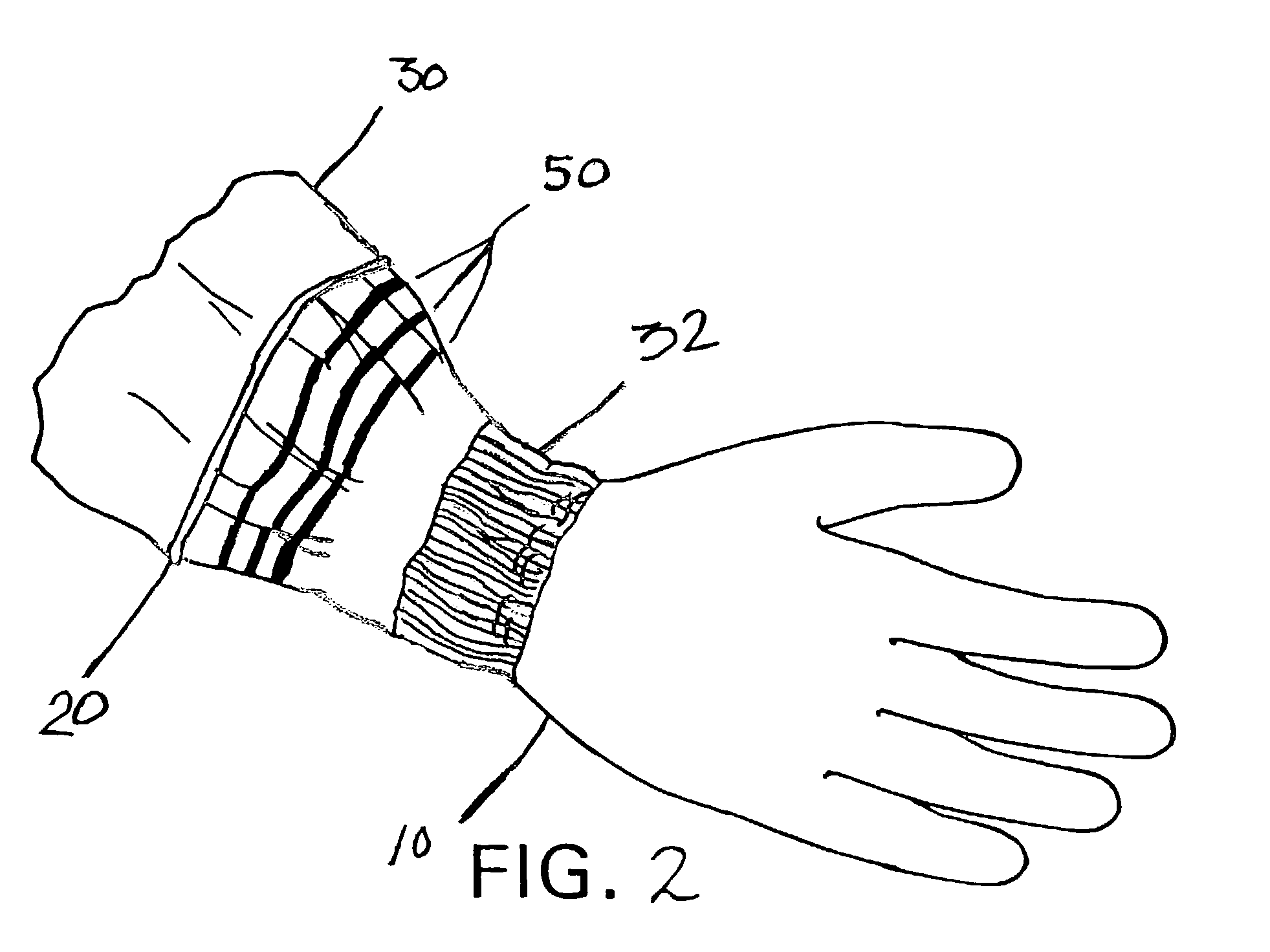
[0011]Protective outerwear for covering a body portion includes an inside surface and an outside surface. The outside surface includes thereupon a printed blocking material in a continuous unbroken band, region, or combination of such, for blocking the wicking of low surface tension liquids at least on the outside surface of the outerwear.
[0012]In an alternative embodiment, the protective outerwear includes low surface tension liquid blocking material on the outside surface in multiple bands. In still a further alternative embodiment the protective outerwear includes low surface tension liquid blocking material on the outside surface in a region. In still a further alternative embodiment, the protective outerwear includes low surface tension liquid blocking material on the outside surface in at least a band and a region. In still a further alternative embodiment the protective outerwear includes low surface tension liquid bloc

Problems solved by technology

If such garments are made from monolithic films (without pores) or film composites, such garments may often be uncomfortable to wear for an extended period as they restrict the ability of air to easily pass through them.
If such garments are made of fibrous material, but are additionally coated with certain film-like coatings to provide a moisture barrier, such materials are likewise uncomfortable to wear.
While such garments may provide high barriers to liquids that may be present in a hospital setting, such garments are often uncomfortable since they fail to breathe in these same large protected areas.
Further, if large areas of such garments are coated with a liquid barrier, such film coating may fail to provide the necessary coefficient of friction which is required for the sustained placement of a glove over such materials, as is the practice in a ho

Method used


Image

  • Anti-wicking protective workwear and methods of making and using same
  • Anti-wicking protective workwear and methods of making and using same
  • Anti-wicking protective workwear and methods of making and using same

Examples


example

Material Example

[0102]In an example of the structure and method of making the structure, a line approximately one quarter inch across that tapered to one sixteenth of an inch across was produced on nonwoven medical gown material using a hot melt wax ink with a melting point of 125° C. and a Spectra Nova piezo-crystal printhead. (the GALAXY PH 256 / 80 HM) In particular, the material was cut from a roll of fabric (MicroCOOL, available from Kimberly-Clark Corporation, Roswell, Ga.) using a hydraulic press. The fabric described above in detail and in U.S. Pat. No. 6,037,281 was a three-layer laminate of spunbond material (SB), breathable film, and an SMS laminate. The body side or inside surface of the fabric was a 0.75 osy SMS and the exterior or outside surface was a 0.6 osy SB both made of polypropylene. The middle layer of the laminate was a cast film consisting of polypropylene skins and a linear low density polyethylene (LLDPE) core all filled with CaCO3 and stretched to generate m...


PUM

PropertyMeasurementUnit
Thicknessaaaaaaaaaa
Widthaaaaaaaaaa
Thicknessaaaaaaaaaa

Abstract

The present invention relates to protective outerwear for covering a body portion. The protective outerwear has an inside surface and an outside surface, with at least the outside surface including thereupon an ink jet printed low surface tension liquid blocking material in a continuous unbroken band, region, or combination of such, for blocking the wicking of liquid that is contained on the outside surface of the outerwear.

Description

TECHNICAL FIELD[0001]The present invention pertains to protective workwear. More specifically, the present invention pertains to medical gowns, surgical gowns and other protective workwear that offer additional contamination protection to users of such workwear, and methods of making and using the same.BACKGROUND OF THE INVENTION[0002]With the burgeoning costs of medical care, and the sterilization costs associated with cleansing medical supplies that may have been exposed to blood borne pathogens and other contaminants, manufacturers of medical supplies such as medical equipment and protective medical apparel, have sought to reduce costs of such supplies to medical service providers. In this regard, medical supply manufacturers have turned to the production of disposable medical supplies so as to reduce the medical costs (in time and labor) associated with cleaning and sterilization, and to provide enhanced options to medical service providers for products that need not be reused. ...

Claims


Application Information

Patent Timeline
IPC IPC(8): A41D13/12A41D19/00A41D27/10A41D27/24A61B19/04A61B19/08
CPCA41D13/1209A41D19/0089A41D27/10A61B19/04A41D27/245A61B19/088A61B19/08A61B42/00A61B46/00A61B46/40
Inventor SCHORR, PHILLIP ANDREWJAMESON, LEE KIRBYSHARMA, VARUNESH
Owner O&M HALYARD INC
Why Eureka
Try Eureka