Axial swage tool

a swage tool and tool body technology, applied in the field of swage tools, can solve problems such as excessive wear, and achieve the effect of easy jamming or binding

Active Publication Date: 2007-01-02
DESIGNED METAL CONNECTIONS
View PDF16 Cites 18 Cited by
  • Summary
  • Abstract
  • Description
  • Claims
  • Application Information

AI Technical Summary

Benefits of technology

[0010]The present invention is embodied in an axial swaging tool having a drop-in piston, i.e., a movable jaw unit, and a stationary piston rod that effectively react moments on the piston during a swaging operation. The design of the tool, with the features described below, contributes to a balanced swaging tool that is typically compact, lightweight, and simple. Furthermore, the swaging tool of the present invention is typically robust, simple to operate, reliable in use, and relatively low in maintenance.
[0014]Many embodiments of the invention also feature a spring compressed between a stop on the piston rod and the piston. The piston is compressively held between the spring and the ram, and a piston rod end is compressively biased to be stationary, with respect to the housing, by the spring. The spring becomes further compressed by the ram when driving the piston axially along the piston rod. The spring provides for the tool to be self-resetting, and provides for the piston rod to be lodged firmly and statically in the chamber without permanently anchoring it or using an attachment that could more easily jam or bind.

Problems solved by technology

Furthermore, the smaller number and simple arrangement of the parts limit the tolerance build-up, which can otherwise result in the piston engagement member rotating to a less-than-preferred angle with respect to the housing engagement member, and which might require custom machining during manufacture to achieve acceptable tolerances.
Furthermore, the design limits bearing loads from being distributed in an uneven fashion that causes excessive wear.

Method used


Image

  • Axial swage tool
  • Axial swage tool
  • Axial swage tool

Examples


Embodiment Construction

[0025]The invention summarized in the embodiments below and defined by the enumerated claims may be better understood by referring to the following detailed description, which should be read with the accompanying drawings. This detailed description discloses particular preferred embodiments of the invention, set out below to enable one to build and use particular implementations of the invention, and it is not intended to limit the enumerated claims, but rather, it is intended to provide particular examples of them.

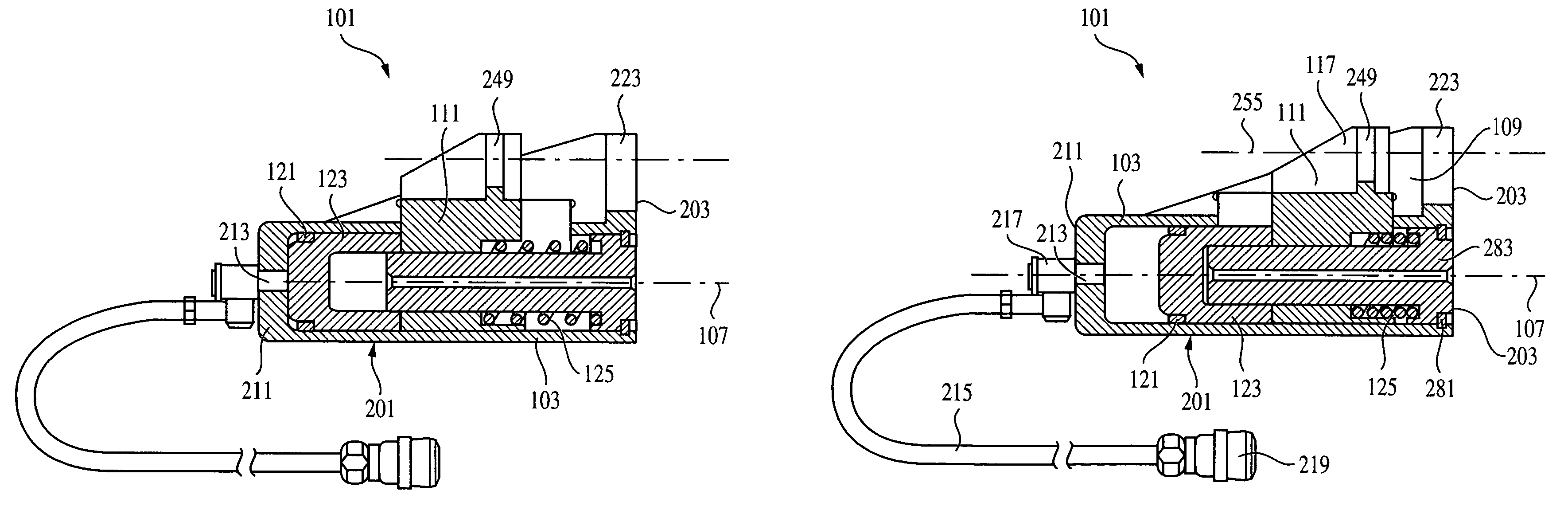
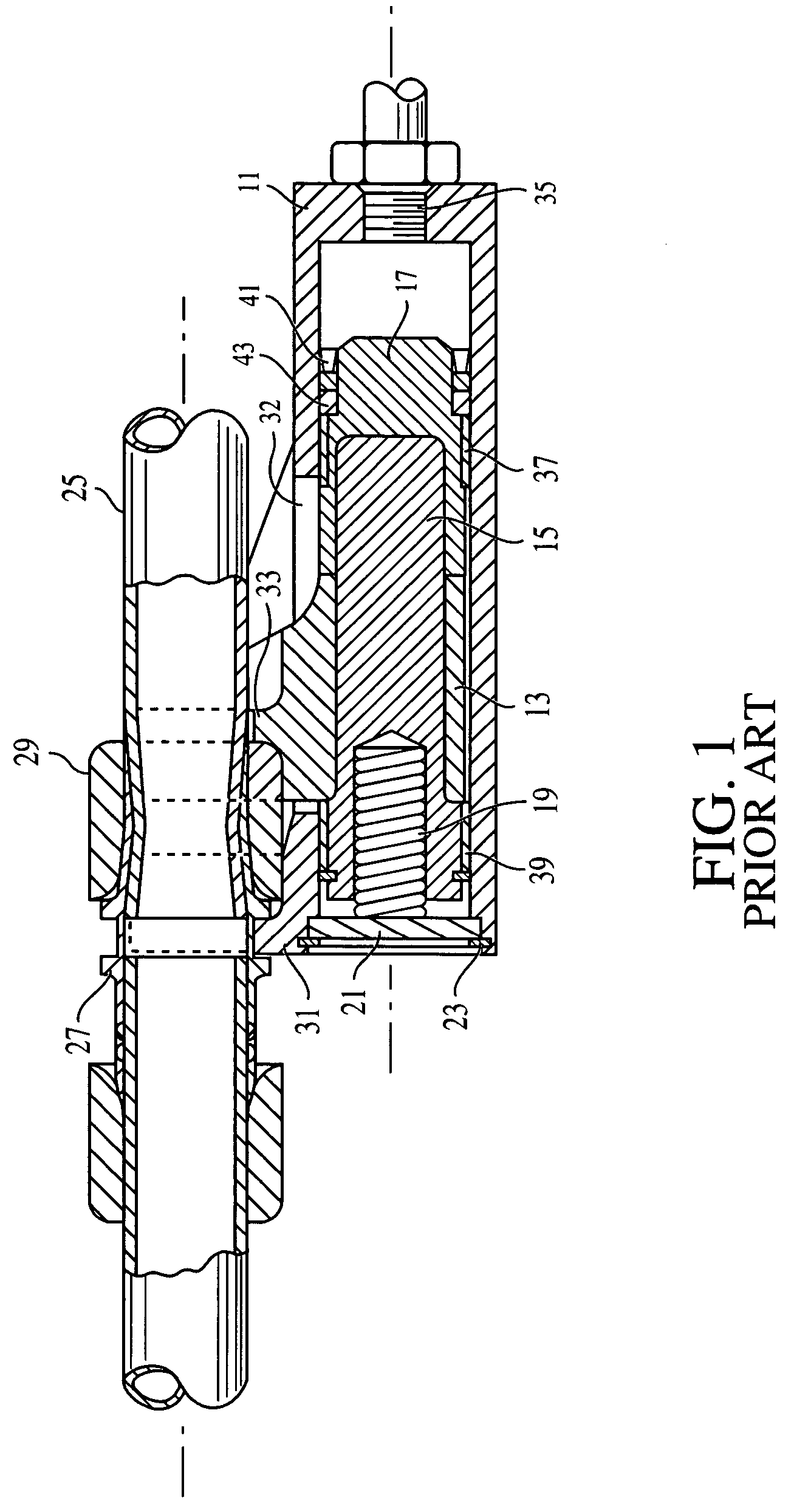
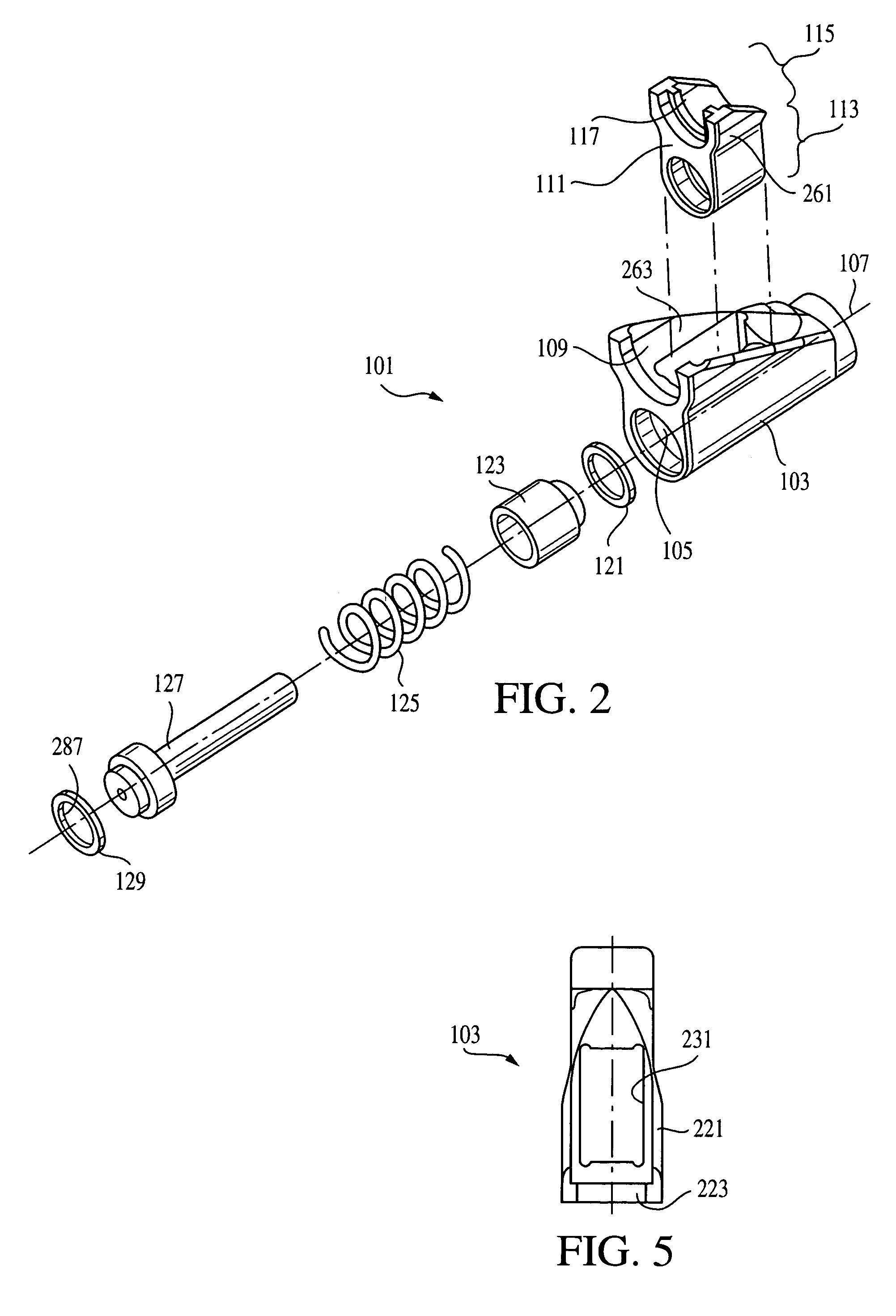
[0026]Typical embodiments of the present invention reside in an axial swaging tool configured to axially swage a fitting to a tube, a cable, or other such item of manufacture. To do so, the swaging tool is typically configured to receive yokes for grasping and driving a swaging ring over the fitting, the swaging ring thereby radially compressing the fitting around the item. The basic grasping and driving mechanics of yokes on rings and fittings to make axially swaged fitt...


PUM

PropertyMeasurementUnit
radial forceaaaaaaaaaa
forceaaaaaaaaaa
circumferenceaaaaaaaaaa

Abstract

An axial swaging tool including a housing defining a chamber, a piston rod held statically in the chamber, a piston conformingly receiving and slidable along the piston rod, a ram conformingly receiving and slidable on a first end of the piston rod, a first engagement member statically positioned on the housing, a second engagement member positioned on the piston, and a spring adjoining the piston and an end of the piston rod. The spring is configured to bias the piston away from a second end of the piston rod, such that the second engagement member is biased away from the first engagement member, the piston rod is biased against a first end of the housing, and piston is biased against the ram, which in turn is biased against a second end of the housing. The ram is made of a bearing material, and carries a seal such that it forms a hydraulically sealed chamber within the chamber at the second end of the housing, the hydraulically sealed chamber to be used with a source of pressurized hydraulic fluid for hydraulically driving the ram and piston toward the first end of the housing, compressing the spring and forcing the second engagement member toward the first engagement member.

Description

[0001]The present application claims the benefit of U.S. provisional application Ser. No. 60 / 512,646, filed Oct. 20, 2003, which is incorporated herein by reference for all purposes.BACKGROUND OF THE INVENTION[0002]The present invention relates to tools for use in swaging and, more particularly, to a swaging tool for swaging axially swaged fittings.[0003]Swaged fittings have been used for many years to connect tubes and pipes in various types of systems, including fluid systems used in the aircraft, marine, petroleum and chemical industries, as well as power transmission systems and the like. In a typical fluid system, the ends of two tubes are inserted into opposing ends of a fitting, each of which is usually in the form of a cylindrical sleeve. The fitting is then swaged with a swaging tool to produce a fluid-tight connection placing the tubes in fluid communication. This swaging operation is normally carried out by applying a radial force that radially compresses the fitting and ...

Claims


Application Information

Patent Timeline
Patent Type & Authority Patents(United States)
IPC IPC(8): B23P19/04B23P11/00B25B27/10
CPCB25B27/10Y10T29/49927Y10T29/5367Y10T29/5383Y10T29/53065
Inventor PALEJWALA, KIRIT M.SASSOON, GILAD S.
Owner DESIGNED METAL CONNECTIONS
Why Eureka
Try Eureka