Heat tunnel for film shrinking

a heat tunnel and film shrinking technology, applied in the field of packaging articles accessories, can solve the problems of increasing aesthetics, increasing complexity, and the current heat tunnels often produce deformed bulls eyes, and achieve the effects of reducing heat energy loss to the environment, reducing wrinkles, and reducing complexity

Inactive Publication Date: 2007-01-02
DOUGLAS MACHINE LIABILITY
View PDF14 Cites 65 Cited by
  • Summary
  • Abstract
  • Description
  • Claims
  • Application Information

AI Technical Summary

Benefits of technology

[0021]A principal object and advantage of the present invention is that a heat tunnel according to a preferred form provides a balanced laminar flow of air through the conveyor and controlled airflow from the sides. This creates shrink film covered packages with consistently shaped bulls eyes, a minimum distortion of graphics, and a minimum of wrinkles.
[0022]Another principal object and advantage of the present invention is that a heat tunnel according to a preferred form permits vertical adjustment of the heat shroud to ensure consistent results over a range of product sizes.
[0023]Another principal object and advantage of the invention is that the heated air passing through the conveyor contacts the film under the product and results in an “air weld” of the film lap seam.
[0024]Another principal object and advantage of the invention is that the heated air has a minimum contact with the product conveyor, so that the conveyor can be maintained at a relatively cool temperature of about 220° F. As a result, the film does not stick to the conveyor and less heat energy is lost to the environment.
[0025]Another principal object and advantage of the present invention is that the outer surface of the heat tunnel stays cooler during operation, thus making the heat tunnel safer and more comfortable to work around and also increasing operating efficiency due to the reduced heat loss.
[0026]Another principal object and advantage of the present invention is improved appearance, with a curved heat shroud and a lower profile.

Problems solved by technology

This is further complicated by product size changeover requirements.
In the packaging industry, aesthetics has become an increasingly important issue, both for the package that is produced and the machine that produces it.
Many of the challenges in producing aesthetically pleasing “bulls eyes” stem from the way that current heat tunnels operate.
Current heat tunnels often produce deformed bulls eyes due to uncontrolled airflow.
That is, as the group of articles enclosed in shrink-wrap film enters the heat tunnel, the film is subjected to various disruptive air currents, causing the film to flutter as it is shrunk.
This uncontrolled airflow results in the film wrinkling and shrinking non-uniformly, which in turn results in unaesthetically pleasing bulls eyes.
Furthermore, current heat tunnels are not generally adjustable for various product sizes.

Method used


Image

  • Heat tunnel for film shrinking
  • Heat tunnel for film shrinking
  • Heat tunnel for film shrinking

Examples


Embodiment Construction

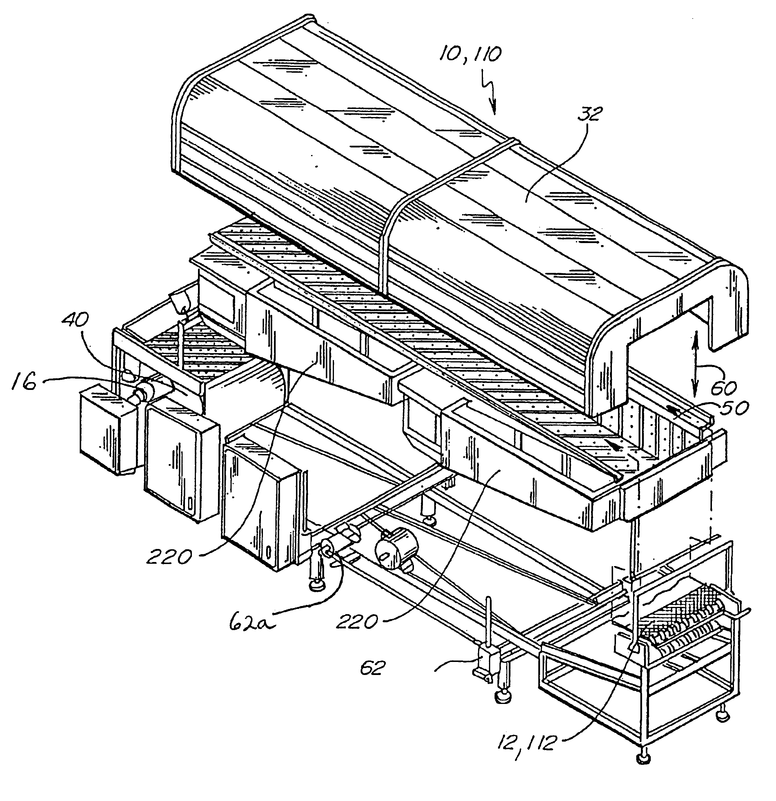
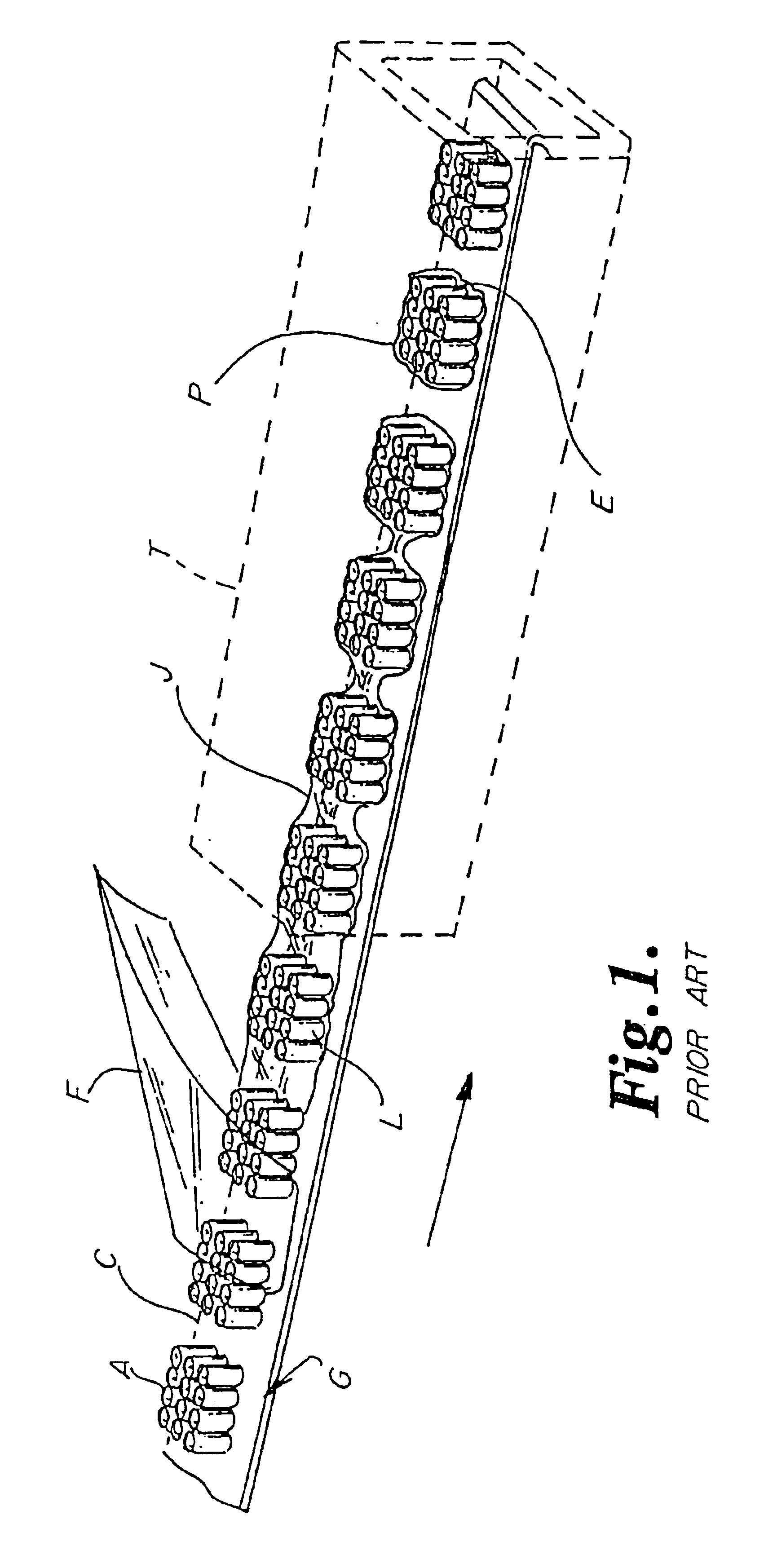
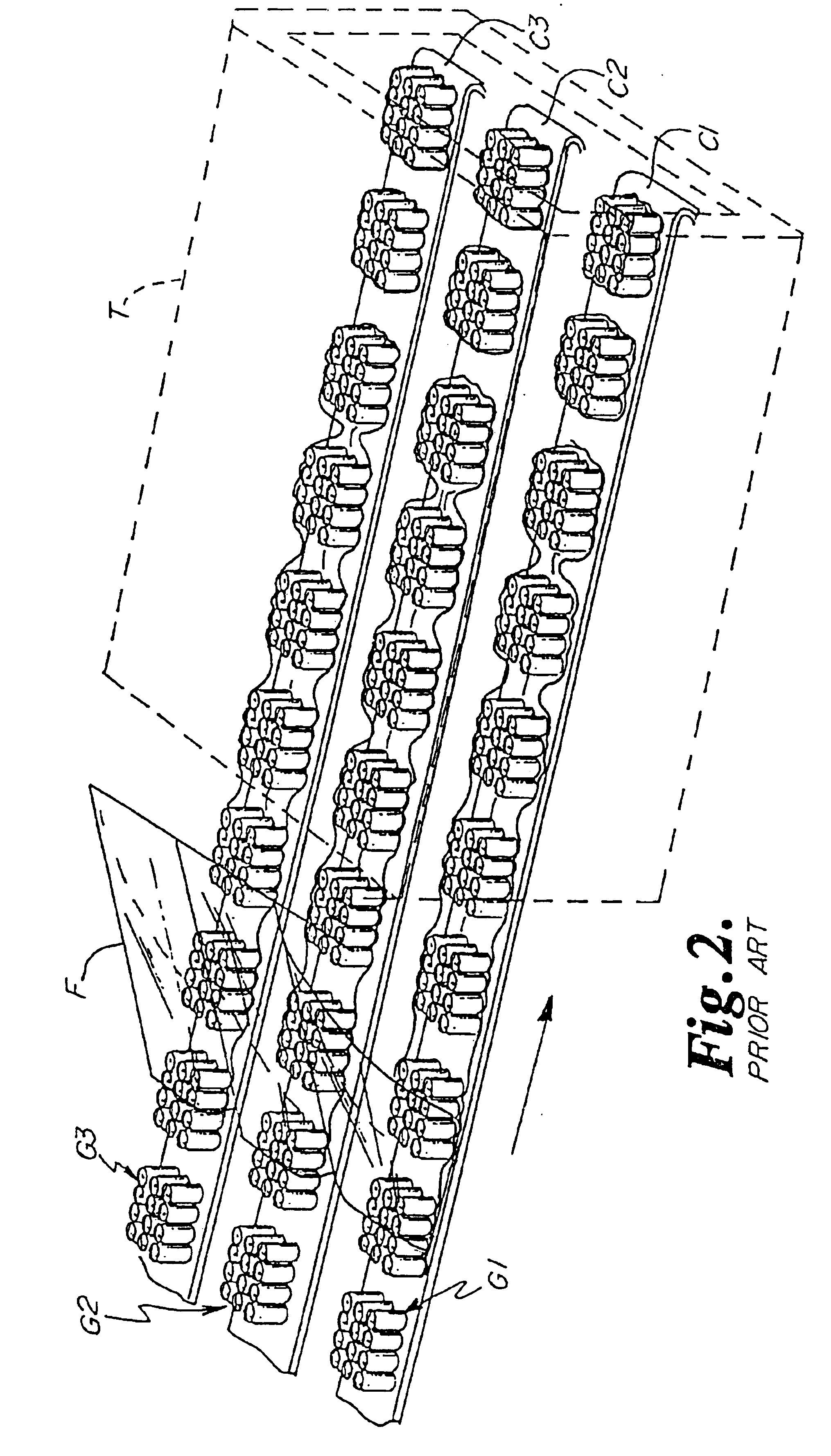
[0057]In one aspect, the present invention is an apparatus 10 for applying heat to articles A and to enclose the articles A in shrink-wrap film F.

[0058]The apparatus 10 (FIGS. 4, 5, and 6) comprises a conveyor 12 having a plurality of first apertures 14 therethrough. A motor 16 drives the conveyor 12 in a first direction as shown by the arrows in FIG. 5.

[0059]The apparatus 10 further comprises a source of heated air 18. The apparatus 10 further comprises (FIG. 7) a heated air plenum 20 under the conveyor 12 and supporting the conveyor 12, the plenum 20 having a top surface 22 having a plurality of second apertures 24 therethrough. It has been found that an optimal size for the second apertures 24 is about 7 / 16 inch to 7 / 32 inch . In this range, the flow of heated air through the apertures 24 is much less turbulent than with either larger or smaller aperture sizes. Specifically, this range of aperture size creates primarily a vertical air flow, while larger aperture sizes allow horiz...


PUM

PropertyMeasurementUnit
temperatureaaaaaaaaaa
heataaaaaaaaaa
areaaaaaaaaaaa

Abstract

A heat tunnel for applying heated air to articles enclosed in shrink-wrap film includes at least one air supply unit; a conveyor; and a heat shroud spaced from the conveyor. Tha air supply unit includes a source of heated air, a fan, a heated air plenum, air ducts, and a return air plenum. Multiple air supply units can be provided along the conveyor to create a heat tunnel of desired length.

Description

CROSS REFERENCE[0001]This application claims the benefit of co-pending U.S. patent application Ser. No. 60 / 473,372, filed May 23, 2003.BACKGROUND OF THE INVENTION[0002]The present invention is directed to an apparatus for packaging articles using shrink-wrap film and, particularly, to an improved heat tunnel that can be used for various film configurations.[0003]It is known in the art to overwrap articles in a web of heat shrinkable film to form a multipack package by separating a tube of such film wrapped around spaced groups of articles along a weakened zone by shrinking the tube adjacent the zone and then by shrinking the tube section formed thereby around the articles to form a package. See U.S. Pat. No. 3,545,165.[0004]Previous methods of packaging such as the above have involved feeding the groups of articles into a heat tunnel in series, with the film wrapped around the articles from the leading edge of the group to the trailing edge of the group. FIG. 1 shows how this is typ...

Claims


Application Information

Patent Timeline
Patent Type & Authority Patents(United States)
IPC IPC(8): B65B53/02B65B53/06B65B9/06B65B61/12
CPCB65B61/12B65B53/063B65B9/06
Inventor VANDERTUIN, BRADLEY JONSCHOENECK, RICHARD JEROMEPAZDERNIK, IRVAN LEOPETERSON, BRUCE MALCOLMWAGNER, PAUL HOWARD
Owner DOUGLAS MACHINE LIABILITY
Why Eureka
Try Eureka