Piping structure for air conditioner

a technology for piping structure and air conditioner, which is applied in the direction of domestic cooling apparatus, lighting and heating apparatus, heating types, etc. it can solve the problems of generating serious vibration of the compressor, weakening the strength of the piping structure in the whole up and down direction, and unable to actively cope with a wide range of specific frequency

Inactive Publication Date: 2007-01-02
LG ELECTRONICS INC
View PDF3 Cites 0 Cited by
  • Summary
  • Abstract
  • Description
  • Claims
  • Application Information

AI Technical Summary

Benefits of technology

[0021]Accordingly, one object of the present invention is to solve the foregoing problems by providing a piping structure of an air conditioner, capable of actively coping with a wide range of specific frequency according to an operation condition (sleep / general / recover in an inverter air conditioner, of protecting components from a vibration and providing a sufficient life span to the components by efficiently damping the vibration transmitted from a compressor to a whole outdoor unit, and of increasing convenience of a consumer by decreasing a noise caused by the vibration.
[0025]The low-vibration piping structure according to the invention can remarkably damp the vibration transmitted from the compressor to the whole outdoor unit, and widen a change range of the specific frequency of the air conditioner.
[0026]Further, the low-vibration piping structure according to the invention can reduce the vibration by an interference phenomenon, which is generated when either a refrigerant pulsation or a periodic vibration of the compressor is divided and then combined.

Problems solved by technology

Meanwhile, the compressor 150 generates serious vibration during a compression process.
However, in the conventional piping structure around the compressor as mentioned above, the piping structure has a weak strength in an up and down direction as a whole.
Further, in the case of application to an inverter air conditioner, the piping structure fails to actively cope with a wide range of specific frequency depending on operation condition of the air conditioner.
Thus, this results in a problem in that energy of the vibration generated from the compressor and then transmitted to the whole outdoor unit can not be efficiently damped.

Method used


Image

  • Piping structure for air conditioner
  • Piping structure for air conditioner
  • Piping structure for air conditioner

Examples


Embodiment Construction

[0035]The following detailed description will present a low-vibration piping structure of an air conditioner according to a preferred embodiment of the invention in reference to the accompanying drawings.

[0036]First, the piping structure of the air conditioner according to the invention will be schematically described.

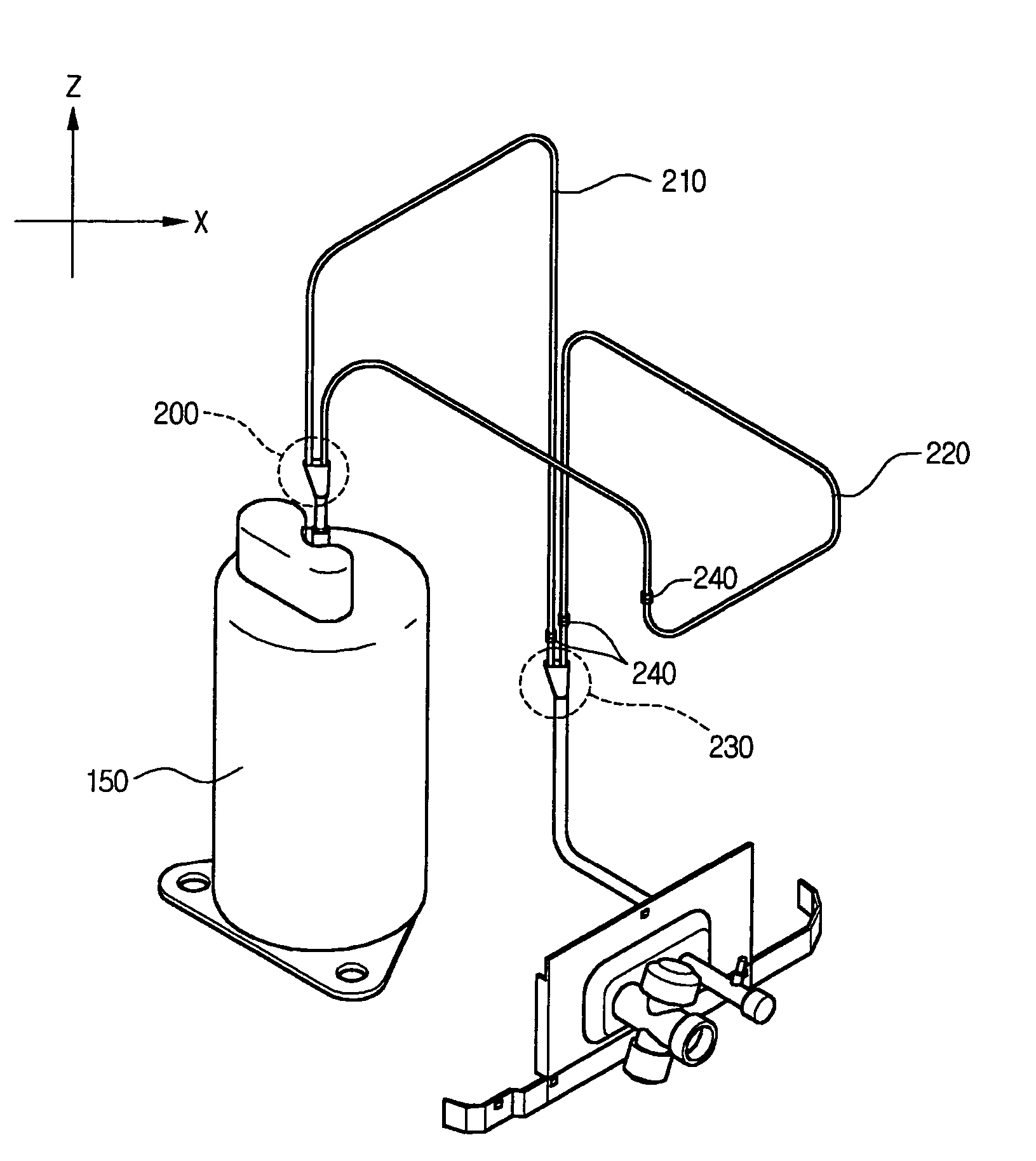
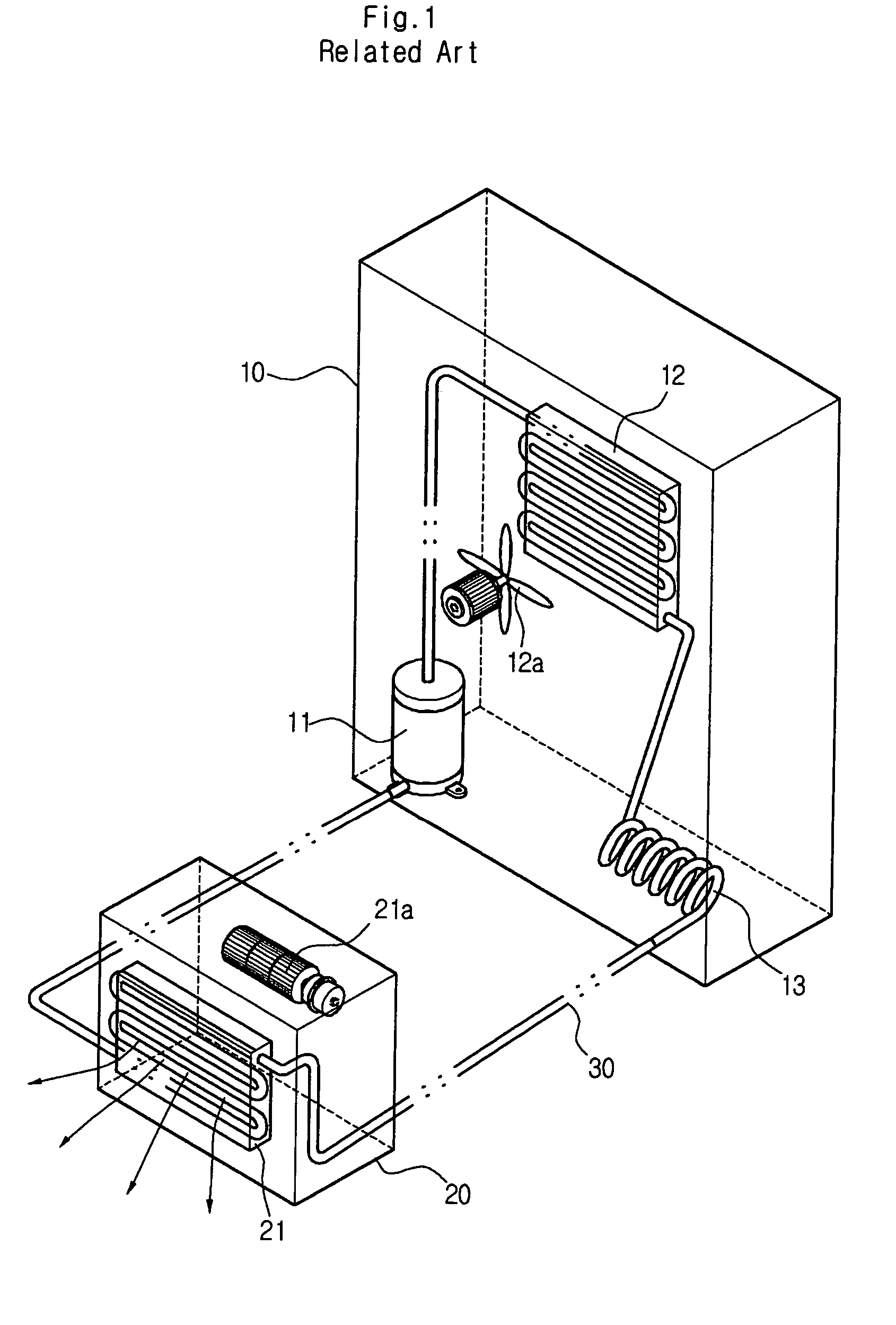
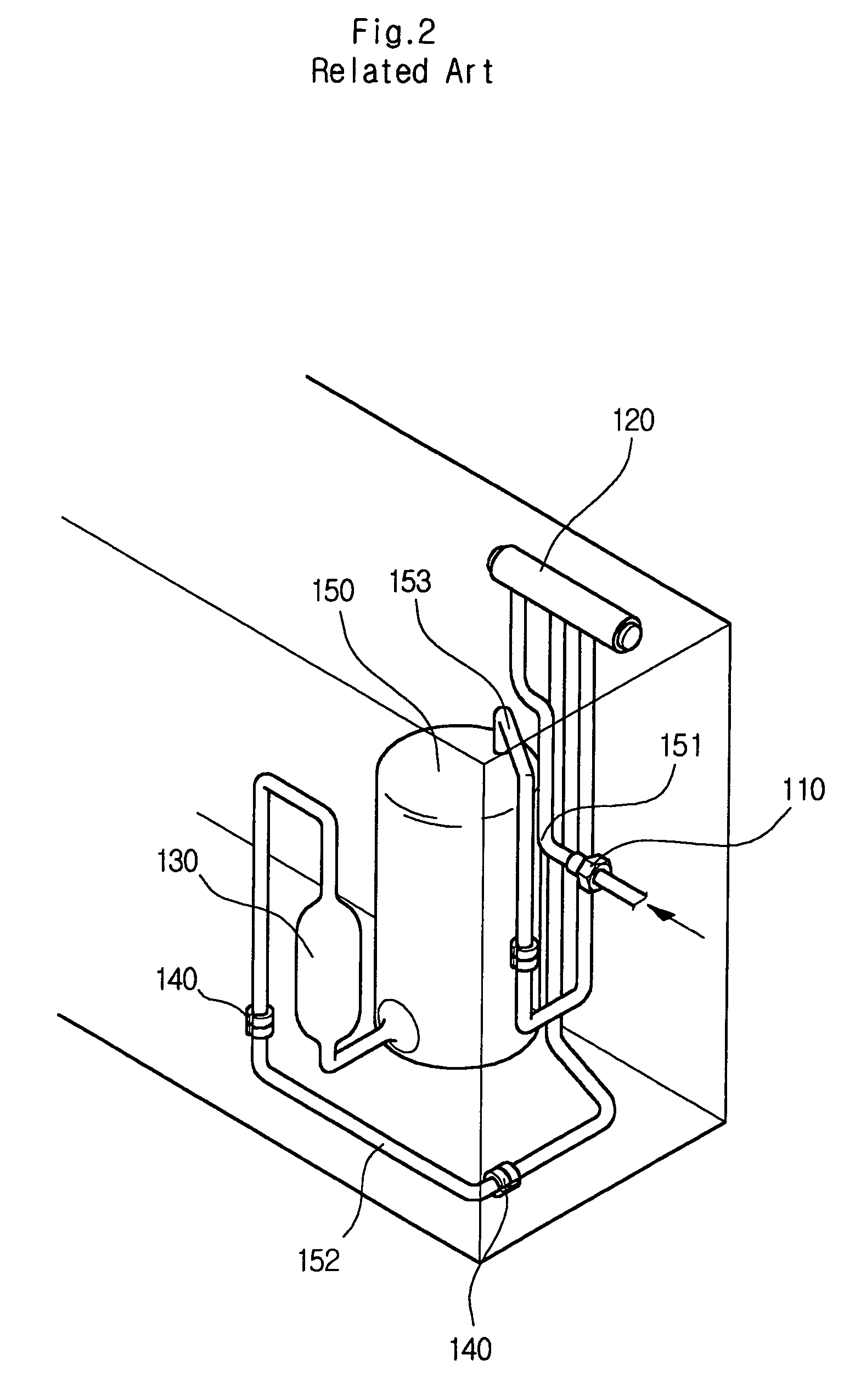
[0037]In the air conditioner, compressor pipings of an outdoor unit are inevitably connected between a compressor and a chassis, thus transporting refrigerant and simultaneously transmitting a vibration of the compressor to the chassis. This is responsible for a structural noise.

[0038]In the case of a constant-speed type air conditioner, to reduce transmission of the vibration, the pipings are subjected to looping. Thereby, a specific frequency of the pipings is tuned, so that the transmission of the vibration generated originally is avoided at an operation frequency. However, in the case of an inverter air conditioner having a wide operation range, it is not easy to t...


PUM


Abstract

A piping structure of an air conditioner causes a looped main piping connected to a compressor of an outdoor unit of the air conditioner to be branched into two or more branch pipings within a predetermined interval of the main piping and cause the branch pipings to be jointed at an arbitrary location. According to the piping structure, it is possible to reduce a vibration by an interference phenomenon, which is generated when either a refrigerant pulsation or a periodic vibration of the compressor is divided and then combined.

Description

[0001]This Nonprovisional application claims priority under 35 U.S.C. § 119(a) on Patent Application No(s). 10-2003-0062109 filed in KOREA on Sept. 5, 2003, the entire contents of which are hereby incorporated by reference.BACKGROUND OF THE INVENTION[0002]1. Field of the Invention[0003]The present invention relates to a piping structure for an air conditioner, and more particularly to a piping structure for an outdoor unit of an air conditioner, designed to minimize influence of a vibration from a compressor by changing a shape of pipings in a way that the pipings are branched and joined in the air conditioner with looped pipings.[0004]2. Background of the Related Art[0005]In general, a compressor refers to a machine used to compress a gaseous medium in various fields. The compressor used in the air conditioner where compression, condensation, expansion and evaporation are sequentially generated is used for compression.[0006]FIG. 1 is a schematic view showing a conventional air cond...

Claims


Application Information

Patent Timeline
Patent Type & Authority Patents(United States)
IPC IPC(8): F25B39/04F25D19/00F24F5/00F24F1/12F24F1/30F25B41/00
CPCF24F1/12F24F1/30F25B41/003F24F1/40F25B2500/13F25B2500/01F25B41/40F24F5/00
Inventor LEE, JUNG WOOCHIN, SIM WONJUNG, IN HWAHONG, KEE SOOCHUNG, MOON KEE
Owner LG ELECTRONICS INC
Why Eureka
Try Eureka