
Concrete slurry transporting pipe for concrete pump-car

a technology of concrete slurry and transporting pipes, which is applied in the direction of heat treatment equipment, manufacturing tools, furnaces, etc., can solve the problems of unpredicted impact from outside, transporting pipes are susceptible to continuous propagation of wear, and the surface of components contacting concrete slurry undergoes some levels of continuous wear, so as to improve impact resistance and wear resistance, the effect of low weigh

Inactive Publication Date: 2010-05-20
ECO STEEL +1
View PDF3 Cites 4 Cited by
  • Summary
  • Abstract
  • Description
  • Claims
  • Application Information

AI Technical Summary

Benefits of technology

[0018]The present invention is conceived to solve the problems of the related art as described above, and an aspect of the invention is to provide a concrete slurry transporting pipe for a concrete pump-car which has a comparatively low weight and demonstrates improved impact resistant and wear resistance to corrosion and friction with gravels and sands during transportation of concrete slurry therethrough.
[0019]More specifically, the invention provides a concrete slurry transporting pipe for a concrete pump-car, which includes heat-treated sections providing wear resistance to the pipe when concrete slurry passes at high pressure through the pipe and non-heat treated sections providing impact resistance to absorb impact from the interior and the exterior of the pipe, thereby demonstrating high wear resistance to abrasive wear and improved impact resistance so as to ensure sufficient life span of the pipe. With this configuration, the concrete slurry transporting pipe can be fabricated without heat-treatment after assembling inner and outer pipes or a separate process for press-fitting the inner pipe into the outer pipe, thereby enhancing workability while significantly reducing the likelihood of defect generation during fabrication.

Problems solved by technology

Since concrete slurry is prepared by mixing high hardness materials such as sands and gravels, surfaces of the components contacting the concrete slurry inevitably undergo some levels of continuous wear, pressure from the concrete slurry transported at a high pressure of about 140 bars, and unpredicted impact from outside in some cases during transportation of the concrete slurry.
As such, the transporting pipe is susceptible to continuous propagation of wear while undergoing a considerable level of pressure from the concrete slurry which is transported at a high pressure therein.
In this condition, the transporting pipe is liable to be abruptly fractured by external impact, causing severe accidents.
However, the non-heat treated transporting pipe made of low-carbon steel and having high ductility is likely to be damaged by various impacts when a concrete slurry mixture prepared by mixing water with a basic cement, high hardness sands, gravels, crushed stones, and the like collides with an inner surface of the pipe while passing at high pressure and speed therethrough.
Generally, the transporting pipe undergoes a combination of damages that include interior scratching or abrasive damage caused by friction between the sands or gravels and the inner surface of the pipe, impact damage caused by collision of the sands or gravels against the pipe, and corrosion caused by water and the basic cement in the slurry.
Since the low-carbon steel transporting pipe is not heat-treated and has a very low hardness of Hv 150˜250, the pipe undergoes abrasive wear by high hardness sands and the like contained in the concrete slurry.
However, since there is no separate means for improving wear resistance to such abrasive hardness, the conventional transporting pipe is liable to be worn to the extent of a wear limit after a predetermined period of use.
Further, impact wear occurs on the inner surface of the pipe by gravel and the like in the concrete slurry transported at high pressure through the pipe and reduces lifespan of the pipe together with the abrasive wear, thereby causing the pipe or components thereof to be continuously replaced during the use thereof.
In these methods, however, since the inner pipe is separately fabricated and assembled to the outer pipe after heat treatment, it is difficult to control dimensional deformation of the inner pipe by heat treatment and any severe dimensional error makes it difficult to assemble the inner and outer pipes.
In particular, when the inner pipe is long and deformed during heat treatment, it is difficult to set press-fitting tolerances of the inner and outer pipes when press-fitting the inner pipe into the outer pipe.
Namely, since it is important to prevent separation of the inner and outer pipes assembled to each other (to maintain a separation force of a critical value or more after press-fitting), the press-fitting tolerances cannot be increased above a suitable level.
As a result, a great press-fitting load is often required to press-fit the inner pipe into the outer pipe, thereby causing an increase in size of a press-fitting device and a decrease in economic feasibility.
On the other hand, the method of joining the inner pipe to the outer pipe through heat treatment requires an expensive heat treatment device and cannot achieve uniform joining of all planes by the heat treatment for long pipes.
Moreover, such a double-pipe is heavier than a single-pipe, thereby providing an excessive load to a boom that supports the pipe at a construction site.

Method used


Image

  • Concrete slurry transporting pipe for concrete pump-car
  • Concrete slurry transporting pipe for concrete pump-car
  • Concrete slurry transporting pipe for concrete pump-car

Examples


Embodiment Construction

[0034]Embodiments of the invention will now be described in detail with reference to the accompanying drawings.

[0035]The present invention may be applied to any kind of concrete slurry transporting pipe that can be classified into a delivery elbow having a curved shape and a delivery pipe having a linear shape according to the shape of the pipe, or that can be classified into a swing pipe, a reducing pipe according to operation thereof. A concrete slurry transporting pipe according to one embodiment of the invention is fabricated using a medium-carbon steel pipe that has a circular cross-section.

[0036]According to the invention, the carbon content of the steel pipe for the concrete slurry transporting pipe may vary depending on a fabrication manner. When the steel pipe is fabricated by machining a steel sheet to have a circular shape and welding the circular sheet, the carbon content is set to 0.45 wt % or less for welding, and when the steel pipe is fabricated by drawing or extrudi...


PUM

PropertyMeasurementUnit
Lengthaaaaaaaaaa
Wear resistanceaaaaaaaaaa
Widthaaaaaaaaaa

Abstract

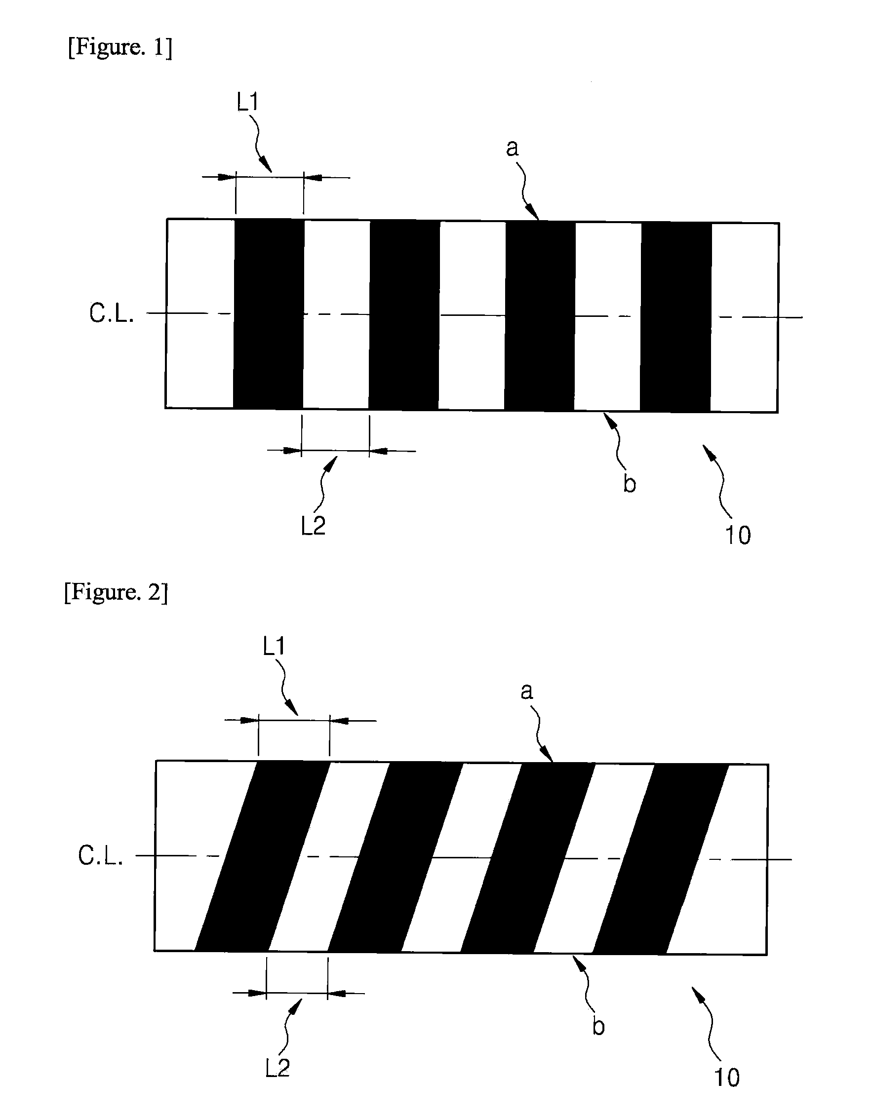
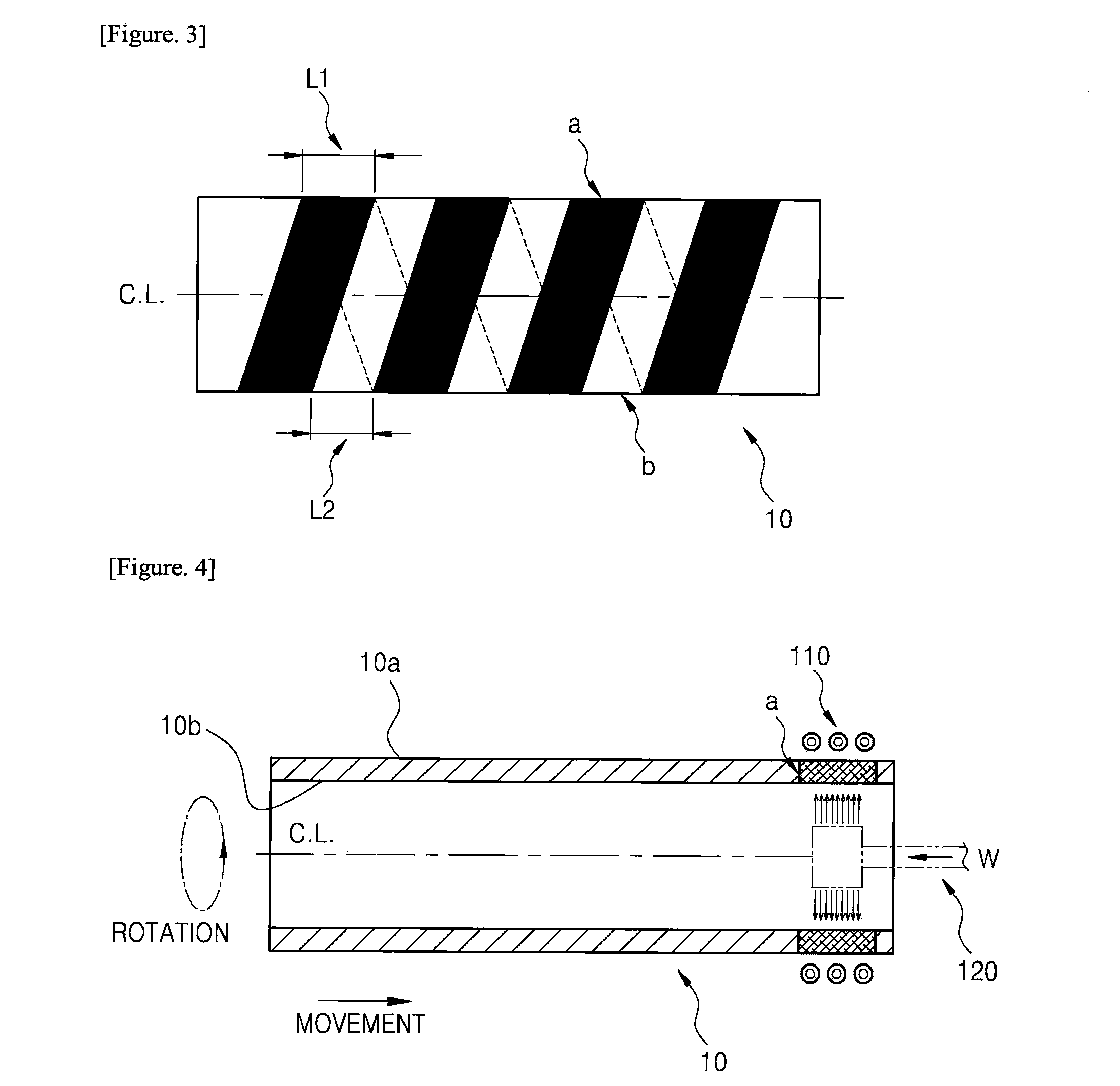
Disclosed is a concrete slurry transporting pipe for concrete pump-cars, which has improved wear resistance to friction with sands or gravels and impact resistance during transportation of concrete slurry. The pipe is a steel pipe made of carbon steel, and includes a heat-treated section having a hardness of Hv 450 or more and formed by induction-heating a portion of an inner or outer surface of the pipe, followed by cooling the heated portion of the inner or outer surface to harden the heated portion, and a non-heat treated section adjoining the heat-treated section. The heat-treated section and the non-heat treated section are alternately formed in a spiral band arrangement along a length of the pipe, and the heat-treated section has a greater width than the non-heat treated section.

Description

BACKGROUND OF THE INVENTION[0001]1. Field of the Invention[0002]The present invention relates to concrete slurry transporting pipes for concrete pump-cars used and, more particularly, to concrete slurry transporting pipes for concrete pump-cars, which demonstrate improved wear resistance and impact resistance to external impact on an inner periphery of the pipe undergoing severe wear when concrete slurry is transported through the pipe.[0003]2. Description of the Related Art[0004]In general, a concrete pump-car (pump truck) is a tool for forcibly transporting concrete slurry (or cement mortar slurry, hereinafter referred to as the “concrete slurry”), received in the form of ready-mixed concrete, i.e., remicon, from a remicon vehicle through a hopper at a construction site, to a higher position of a tall building or the like under construction by pumping the concrete slurry while pressing it in a hydraulic cylinder.[0005]Such a concrete pump car includes a cylinder unit compressing c...

Claims


Application Information

Patent Timeline
IPC IPC(8): F16L9/22
CPCC21D2221/00C21D9/14C21D9/08C21D1/06C21D1/42B65G33/04
Inventor JEONG, JIN-HYUN
Owner ECO STEEL
Learn More