Micro angular rate sensor

a micro-angular rate and sensor technology, applied in the direction of turn-sensitive devices, acceleration measurement using interia forces, instruments, etc., can solve the problems of measurement error, measurement difficulty increase, measurement error, etc., and achieve greater coriolis force, greater mass, and greater intensity

Inactive Publication Date: 2007-01-02
NAT CHUNG SHAN INST SCI & TECH +1
View PDF11 Cites 60 Cited by
  • Summary
  • Abstract
  • Description
  • Claims
  • Application Information

AI Technical Summary

Benefits of technology

[0015]In accordance with the principle of the invention, a resonant structure having greater mass is provided in the sensing device to increase the signal-sensing area. Meanwhile, the sensing structure does not need a high aspect ratio manufacturing process.
[0022]According to the aspect and principle of the invention, the micro angular rate-sensing device has another advantage of increasing sensing areas and the sensing intensity of signals.
[0023]According to the aspect and principle of the invention, the micro angular rate-sensing device has another advantage of a lower requirement for the high aspect ratio manufacturing process. Therefore, the manufacture cost may be reduced and the yield rate increased.
[0024]According to the aspect and principle of the invention, the micro angular rate-sensing device has symmetrical flexible supporting members such that the resonant frequency of the sensing mode and driving mode in all directions become substantially the same for greater frequency match. Therefore, better amplification of amplitude sensitivity may be obtained. Furthermore, the resultant Coriolis force may be directed to the node of the driving mode. The error of the zero rate output (ZRO) and the cross-axis sensitivity may also be reduced effectively.
[0025]According to the aspect and principle of the invention, the micro angular rate-sensing device has another advantage of high precision and low cost.

Problems solved by technology

Due to the constraints of Microelectromechanical manufacturing technology and the consideration of endurance, most gyroscopes are vibratory.
However, the aforementioned related art has some technical problems that need to be solved.
The supporting structure is not symmetrical so that the resultant Coriolis force does not indicate the original node, which may cause measurement error.
Also, the signal-sensing area is not large enough so that the intensity of the signals is small, and therefore the difficulty of measurement increases.
Although the high aspect ratio manufacture technology may reform these problems, the expense and machine investment may be prohibitive.

Method used


Image

  • Micro angular rate sensor
  • Micro angular rate sensor
  • Micro angular rate sensor

Examples


Embodiment Construction

[0033]Reference will now be made in detail to the embodiments of the invention, examples of which are illustrated in the accompanying drawings. Reference in the specification to “one embodiment” or “an embodiment” means that a particular feature, structure, or characteristic described in connection with the embodiment is included in at least one embodiment of the invention. The appearances of the phrase “in one embodiment” in various places in the specification are not necessarily all referring to the same embodiment.

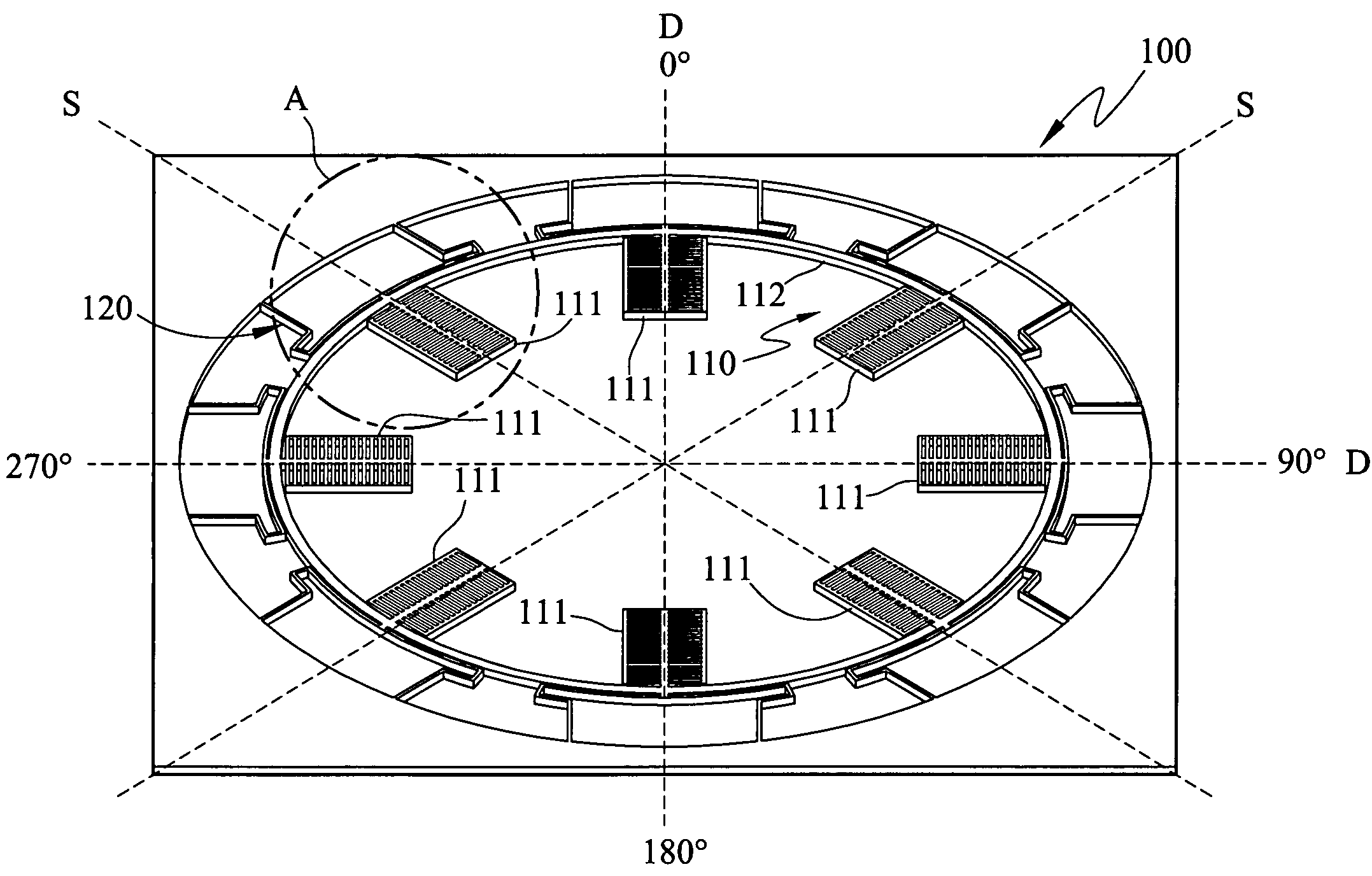
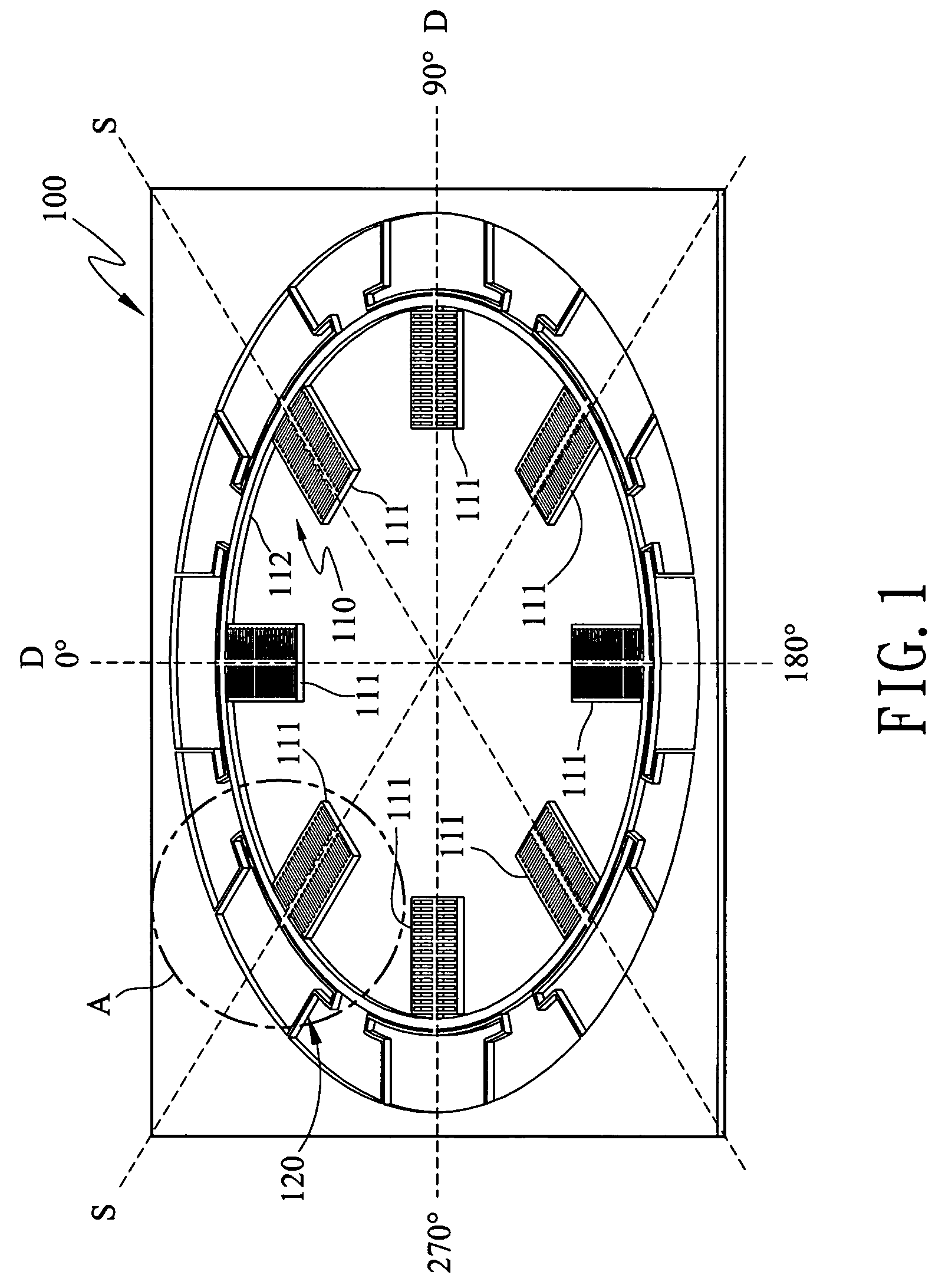
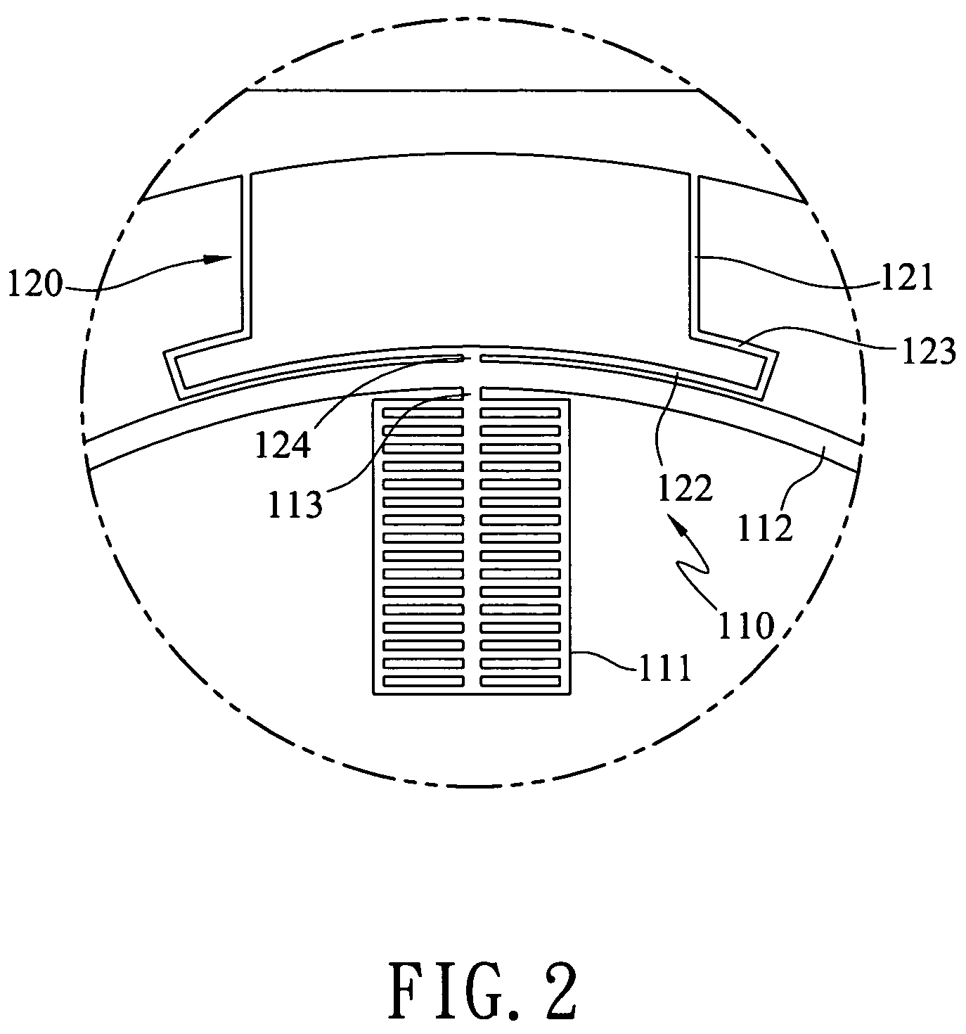
[0034]Refer FIG. 1 and FIG. 2. FIG. 1 the schematic structure of the angular rate-sensing device in accordance with the invention, while FIG. 2 is the enlarged diagram of the A portion in FIG. 1. According to the principle of the invention, the micro angular rate-sensing device includes a first base 100, a vibrator 110 having multiple proof masses and a plurality of flexible supporting members 120. The vibrator 110 arranged on the first base 100 has a plurality of proof...


PUM


Abstract

A micro angular rate-sensing device is provided. A vibrator, having a plurality of proof masses connected to a ring, is arranged in a first base. Flexible supporting members connect to the vibrator to suspend the vibrator in the first base. Electrodes drive the vibrator to oscillate and control the oscillation mode of the vibrator in driving mode. Planar electrodes are arranged relative to the proof masses on a second base. The motion of the proof masses relative to the planar electrodes is sensed through the capacitance between the proof masses and the planar electrodes. The resonant structure with greater mass of the device generates greater Coriolis force and increases the sensing area. Thus, the intensity of sensed signals and noise-signal ratio are greatly increased. Furthermore, the device does not rely much on high aspect ratio manufacturing technology. Thus the manufacturing cost is reduced and the yield rate is increased.

Description

[0001]This Non-provisional application claims priority under 35 U.S.C. § 119(a) on Patent Application No(s). 093113693 filed in Taiwan, R.O.C on May 14, 2004, the entire contents of which are hereby incorporated by reference.BACKGROUND OF THE INVENTION[0002]1. Field of Invention[0003]The invention relates an angular rate sensing device for an angular rate sensor or a micro gyroscope and, in particular, to an angular rate sensing device having a plurality of proof masses employed as a resonant structure for increasing the signal-sensing areas, such that greater Coriolis force is generated and Coriolis force intensity increases. Furthermore, the sensing areas and the intensity of the sensing signals are increased.[0004]2. Related Art[0005]The gyroscope is a device that measures rotating angles or angular rates by using the inertia principle. One of these is a micro gyroscope manufactured by micro technology. It has been used widely in many fields, such as anti-overturning systems for ...

Claims


Application Information

Patent Timeline
Patent Type & Authority Patents(United States)
IPC IPC(8): G01P9/04G01C19/56G01P9/00
CPCG01C19/5712
Inventor LO, YUANHO, KYE-CHYNLIN, LUNG-YUNGTSENG, CHIH-WEISCHE, SCHIU
Owner NAT CHUNG SHAN INST SCI & TECH
Why Eureka
Try Eureka