Coating machine

a coating machine and coating material technology, applied in the field of coating machines, can solve the problems of high friction, low electric of the coating material, and possible operation of the operating fluid, and achieve the effect of small driving for

Active Publication Date: 2007-01-02
TRINITY IND CORP
View PDF15 Cites 21 Cited by
  • Summary
  • Abstract
  • Description
  • Claims
  • Application Information

AI Technical Summary

Benefits of technology

[0010]In view of the above, it is a technical subject of the present invention to provide a coating material-filled type coating machine capable of discharging under pressure a paint or like other coating material reliably with a small driving force without sliding movement of a bottom plate and, accordingly, with no trouble of decomposing cleaning by detaching the bottom plate.
[0014]Further, since there is no more required to slide the bottom plate, there is no worry of coating failure caused by the leakage in the seal for the bottom late and since there is no gaps through which the coating material intrude, cleaning can be conducted simply.
[0017]Thus, since the contact faces of the coating material bag and the operating fluid reciprocate as if they were a single sheet of diaphragm in the coating material discharge chamber without forcing only the coating material bag, for example, to the corner of the coating material discharge chamber thereby compressing only the coating material bag, this can provide an advantageous effect that respective bags are less creased or broken.

Problems solved by technology

However, since the aqueous coating material has low electric resistance tending to electrically conduct the rotary atomizing head and the ground of the electrostatic coating machine by way of a coating material flowing through a coating material supply system, insulation has to be applied over the entire coating material supply system so as to prevent leakage of high voltage of −60 to 90 kV applied to the rotary atomizing head.
However, since the bottom plate and the inner peripheral surface have to be sealed reliably, friction increases by so much to require a large driving force.
Since the seal is worn by friction on every reciprocation of the bottom plate, an operating fluid may possibly enter to give an undesired effect on the quality of the coating in a case of liquid pressure driving.
Further, since plural O-rings are arranged in parallel to the outer peripheral surface of the bottom plate as a piston in the usual seal, the coating material intrudes between each of the O-rings and this imposes a trouble of decomposing and detaching the bottom plate and clean the same upon cleaning after completion of every day's job.

Method used


Image

  • Coating machine
  • Coating machine
  • Coating machine

Examples


example 2

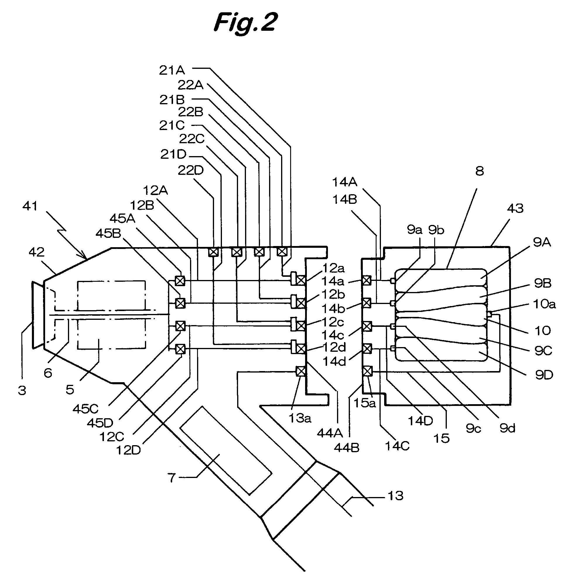
[0051]FIG. 2 is an explanatory view showing another embodiment according to the invention. Those portions in common with FIG. 1 carry same reference numerals for which detailed descriptions are to be omitted.

[0052]In an electrostatic coating machine 41 of this embodiment, coating material inlet / exit ports 9a to 9d and an operating fluid inlet / exit port 10a are formed to a coating material discharge chamber 8 of a cartridge 43 mounted to a machine body 42. Plural coating material bags 9A to 9D for filling aqueous coating materials of respective colors are attached to coating material inlet / exit ports 9a to 9d, and an operating fluid bag 10 for discharging the coating material under pressure is attached to the operating fluid inlet / exit port 10a, respectively, in a detachable manner.

[0053]The coating material bags 9A to 9D and the operational fluid bag 10 are formed each in a tubular or balloon shape having a connection ports formed at one end, each of the connection port is connected...

example 3

[0064]FIG. 3 shows a further embodiment of the invention. Those portions in common with FIG. 1 carry identical reference numerals for which detailed descriptions are to be omitted.

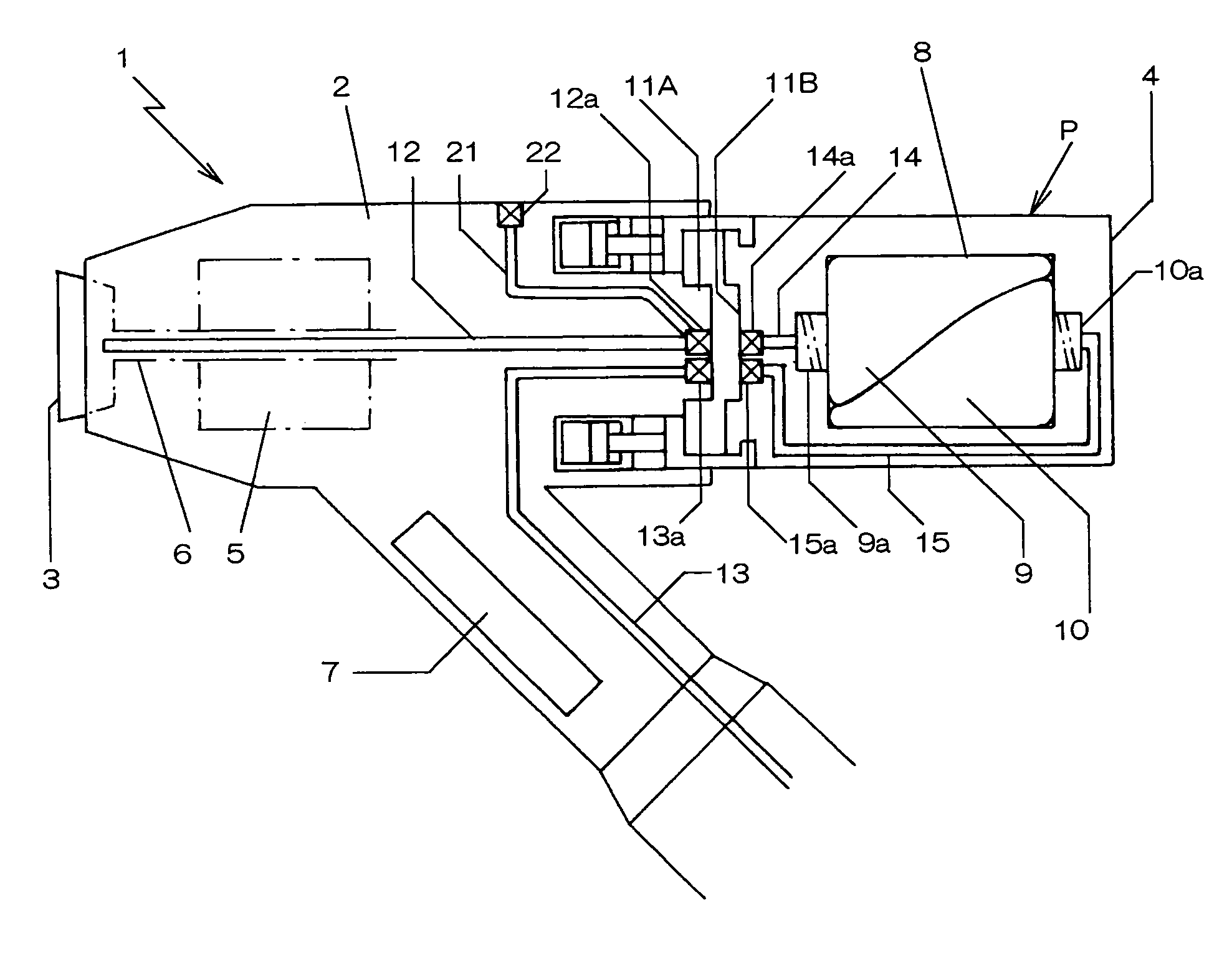
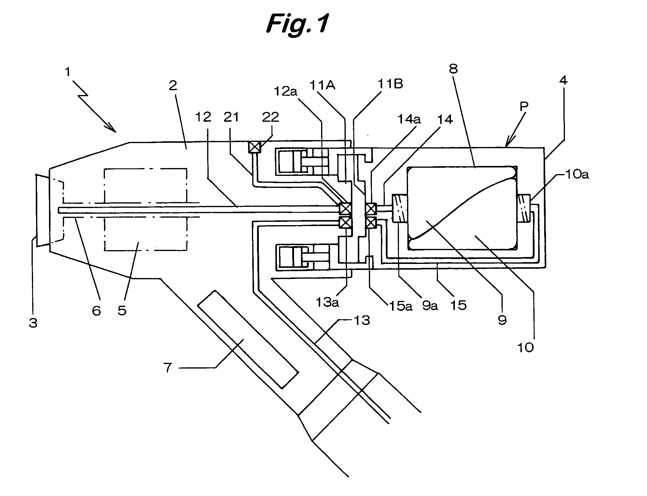
[0065]In a cartridge 34 of an electrostatic charging machine 31 shown in FIG. 3, the front side of a coating material discharge chamber 8 having a cylindrical inner peripheral surface is formed as a lid 44, and the lid 4A is provided with a joint11B to be connected with a joint 11A at the rear end of the machine body 2. The lid 4A is provided with a coating material inlet / exit port 9a for connecting the coating material bag 9 and an operating fluid inlet / exit port 10a for connecting the operating fluid bag 10.

[0066]The ports 9a and 10b are formed with male / female receptacles screw coupling with the male screws formed to the ports for each of the bags 9 and 10 and female screws formed to the lid 4A, and the ports are provided with a stop valves which are opened when the cartridge is mounted to the machine b...


PUM

PropertyMeasurementUnit
voltageaaaaaaaaaa
pressureaaaaaaaaaa
shapeaaaaaaaaaa

Abstract

A coating machine having a coating material discharging mechanism for discharging a previously filled coating material under pressure to an atomizing mechanism wherein a coating material bag for filling a coating material is housed in a coating material discharging chamber of a predetermined volume and an inlet / exit port of an operating fluid is disposed for exerting a pressure from the outside of the coating material bag thereby discharging the coating material under pressure, while crushing the coating material bag, whereby paint or other coating material can be discharged under pressure reliably by a small driving force.

Description

BACKGROUND OF THE INVENTION[0001]1. Field of the Invention[0002]The present invention concerns a coating machine provided with a coating material discharging chamber for previously filling a coating material and discharging the same under pressure to an atomizing mechanism during coating and, more specifically, it relates to an electrostatic coating machine for electrostatically atomizing a conductive coating material such as an aqueous paint.[0003]2. Statement of Related Art[0004]In the coating of car bodies, coating materials using organic solvents are predominant, but it has been demanded to decrease volatile organic solvents that are evolved a great amount in the coating process with a view of environment protection and prevention of public pollution and, as a outer measure, coating with aqueous coating materials has attracted attention.[0005]For using an aqueous coating with no loss, it is preferred to apply coating by an electrostatic coating apparatus of high coating efficien...

Claims


Application Information

Patent Timeline
Patent Type & Authority Patents(United States)
IPC IPC(8): B05C7/02B05D1/04B05B5/00B05B5/04B05B12/14B05C5/02B05C11/00B05C11/10
CPCB05B12/1463B05B5/0407
Inventor UENO, TAKAONOMURA, TAKAO
Owner TRINITY IND CORP
Why Eureka
Try Eureka