
Flush valve and drain system for recreational vehicles

a technology for flushing valves and recreational vehicles, which is applied in the direction of sewage draining, valve housings, transportation and packaging, etc., can solve the problems of user inability to visually observe or determine the cleanliness of flushing or rinsing water, and difficulty in properly aligning, etc., and achieve the effect of convenient detachable connection

Active Publication Date: 2007-01-02
GARST ROGER
View PDF5 Cites 21 Cited by
  • Summary
  • Abstract
  • Description
  • Claims
  • Application Information

AI Technical Summary

Benefits of technology

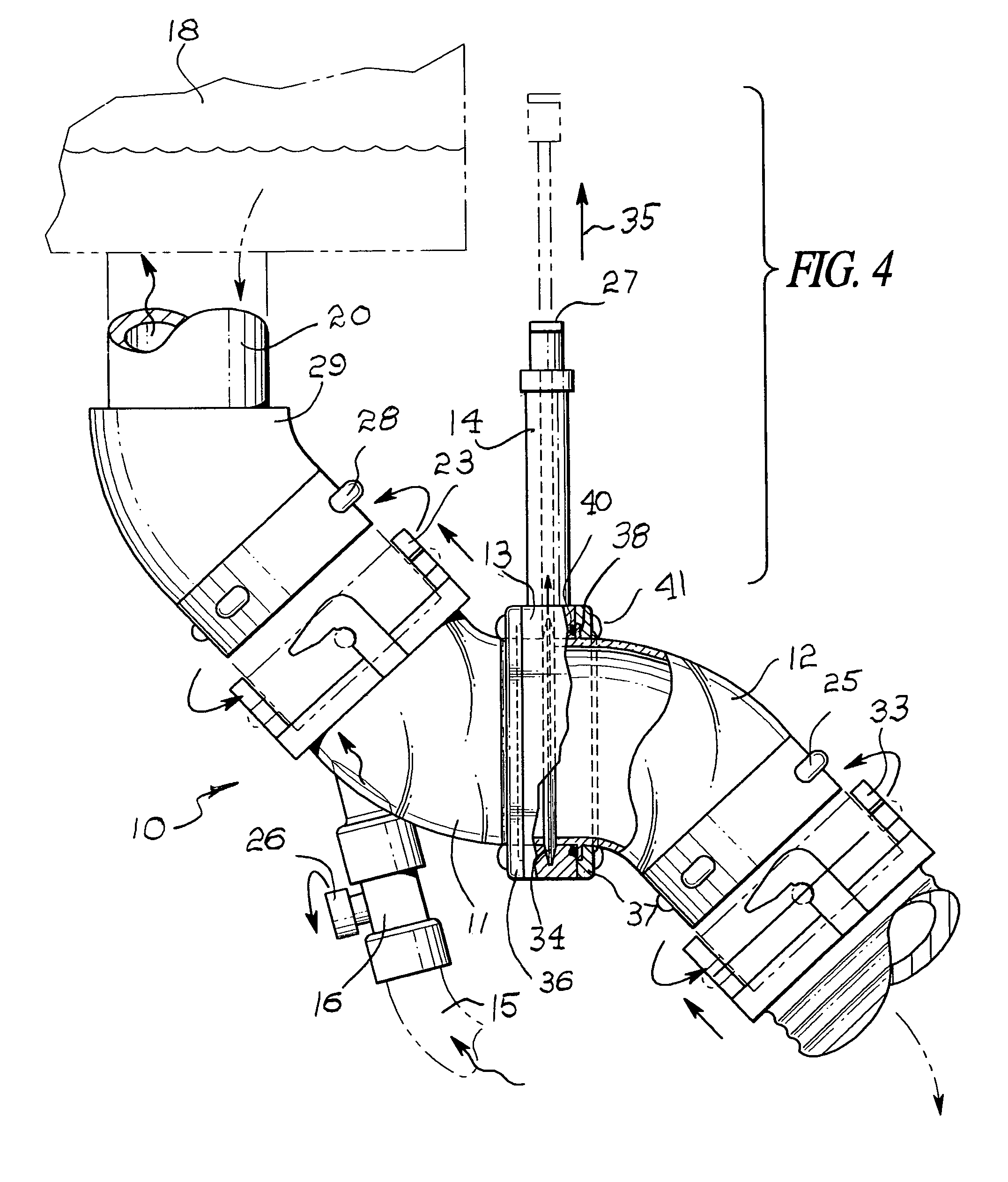
[0007]Accordingly, the above problems and difficulties are avoided by the present invention which provides a novel transparent drain and flush valve component combination that may be readily detachably connected between a vehicle drain outlet and a disposal conduit leading to a sewage receptacle. The apparatus includes a main body having a pair of end plates which are joined to the body by means of fasteners. The end plates and the body are separated by mated flanges adapted to rotate with respect to each other. An elastomeric O-ring between the flanges not only seals but accommodates rotation of transparent attachment pipes for both the vehicle and the disposal conduit. Also, a shut-off valve is included in the body which is manually operated and takes the form of a slide or gate valve which can partially or fully open or close fluid communication between the pair of attachment pipes. A pressurized water supply is selectively attached to an attachment pipe for introducing pressurized water to the vehicle plumbing system, including the holding tank for flushing and rinsing purposes.
[0008]Therefore, it is among the primary objects of the present invention to provide a portable and compact drain assemblage having particular usage in connection with recreational vehicles for cleansing and rinsing sewage holding tanks and which assemblage can readily and efficiently attach to the vehicle plumbing system and to the sewage disposal conduit.
[0010]Still another object of the present invention is to provide a flush valve and drain assemblage for recreational vehicles having rotatable connection for readily aligning the components of the assemblage between vehicle plumbing and a sewage disposal conduit.
[0011]Another object of the present invention is to provide a flush valve and drain assemblage having components which are composed of a transparent or translucent material so that the cleansing and rinsing fluid within the assemblage can be visually observed and evaluated for cleanliness and density during a cleaning procedure.
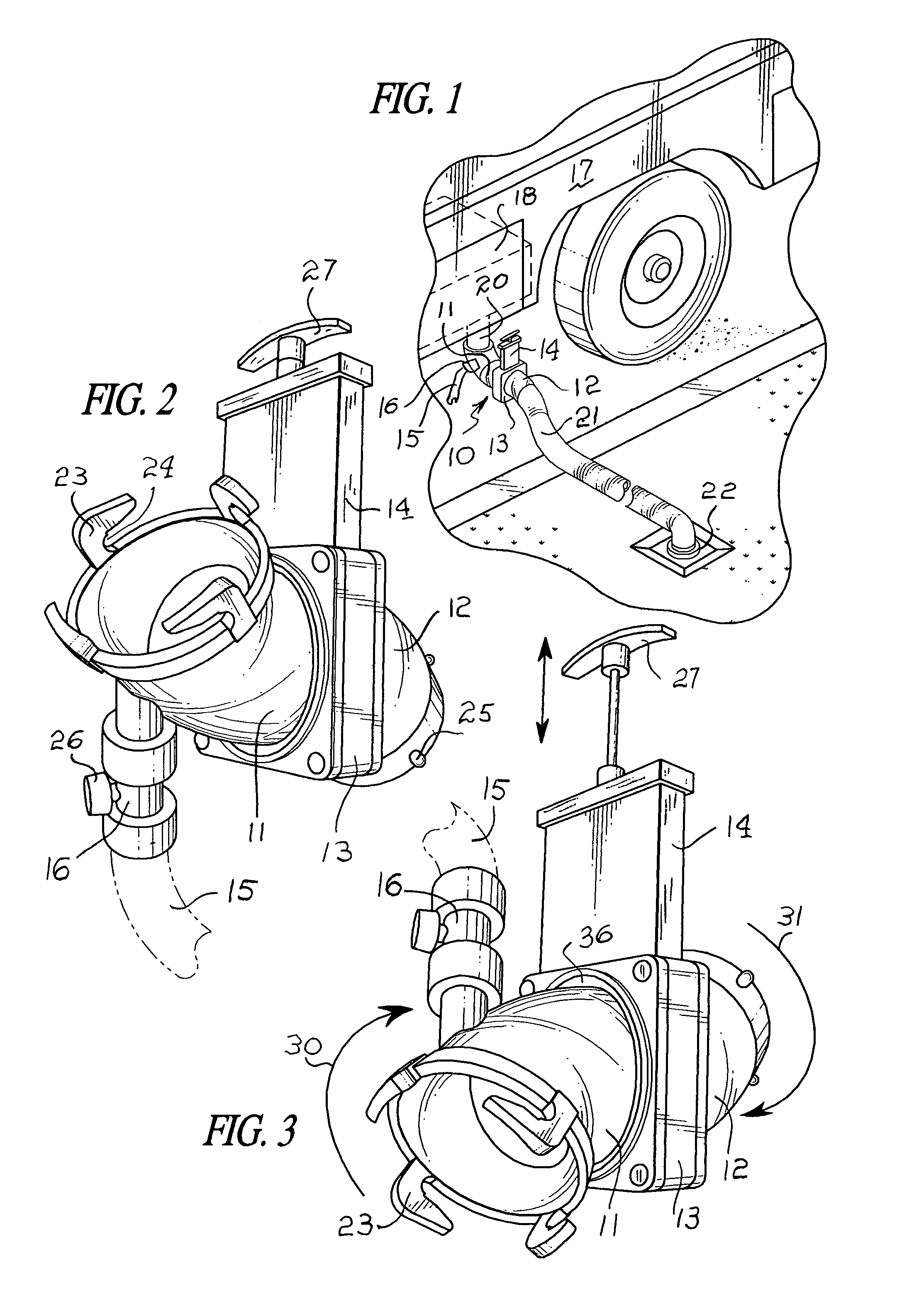
[0012]A further object resides in a flush valve and drain assemblage having a clear 45-degree pipe which rotates a complete 360 degrees independently around the valve blade body thus enabling the valve to operate from any position and wherein rotation of the barrel allows greater flexibility for the user with the various tightly configured holding tank drain valves and plumbing.

Problems solved by technology

In conventional systems, it has been difficult to properly align, support and connect the drainage apparatus and associated valving with the plumbing outlet from the vehicle draining system to a drainage disposal conduit so that a flushing supply of water can be introduced into an empty holding tank in order to rinse and clean the tank.
These difficulties stem largely from the fact that the drain and valve fittings are fixed and do not permit rotation alignment or even secure attachment to the vehicle draining outlet or to the inlet of the drainage conduit.
Also, inasmuch as the drainage and flush valve components are opaque, the user can not visually observe or determine cleanliness of the flush or rinse water as the water is conducted through the components.

Method used


Image

  • Flush valve and drain system for recreational vehicles
  • Flush valve and drain system for recreational vehicles
  • Flush valve and drain system for recreational vehicles

Examples


Embodiment Construction

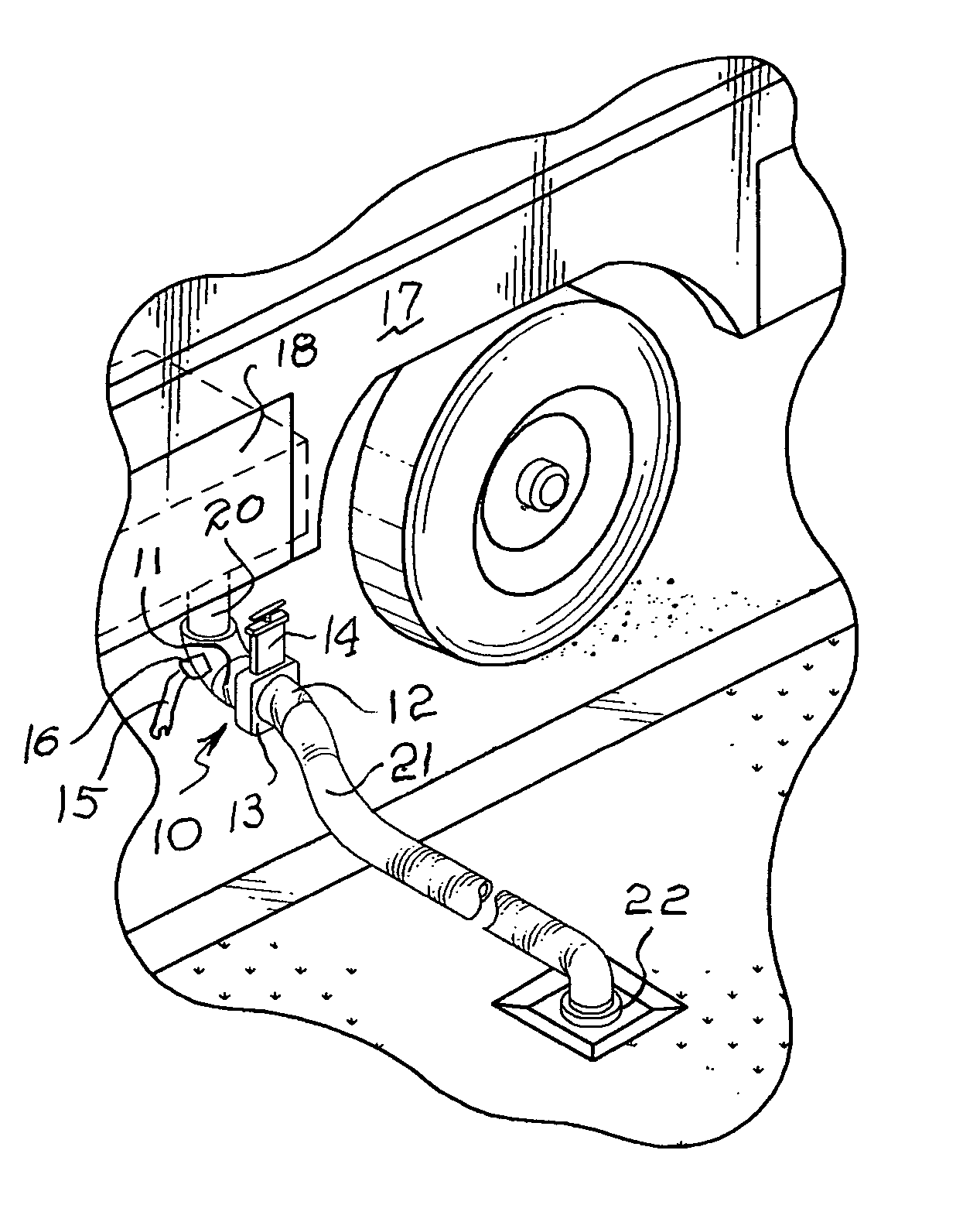
[0020]The flush valve and drain assemblage is illustrated in the general direction of arrow 10 in FIG. 1 which includes a first joint or inlet pipe component 11 and a second joint or outlet pipe component 12 which are rotatably mounted on opposite sides of a body 13. A shut-off valve, which is manually operated, is indicated by numeral 14. A source of pressurized fluid, such as water, is introduced to the assemblage via a hose 15 which is connected to the first inlet pipe component 11 via a valve 16. The inlet and outlet pipes are clear or transparent 45-degree barrels that have the ability to rotate 360 degrees independently of each other about the flush valve body 13.

[0021]The flush valve and drain assemblage 10 is interconnected between the plumbing of a recreational vehicle 17 which includes a holding tank 18, illustrated in broken lines, and an outlet 20 to which the first pipe component 11 is detachably connected. The second pipe component 12 is detachably coupled to a disposa...


PUM


Abstract

A transparent drain and flush valve component combination detachably connected between a vehicle drain outlet and a disposal conduit which leads to a sewage receptacle. The apparatus includes a main body having a pair of end plates which are joined to the body by fasteners. The end plates and the body are separated by mated flanges adapted to rotate with respect to each other. An elastomeric O-ring between the flanges not only seals but accommodates rotation of transparent attachment pipes for both the vehicle and the disposal conduit. Also, a shut-off valve is included in the body which is manually operated and takes the form of a slide or gate valve which can partially or fully open or close fluid communication between the pair of attachment pipes. A pressurized water supply is selectively attached to an attachment pipe for introducing pressurized water to the vehicle plumbing system, including the holding tank for flushing and rinsing purposes.

Description

[0001]This application claims the benefit of U.S provisional application No. 60 / 463,012, filed on Apr. 15, 2003.BACKGROUND OF THE INVENTION[0002]1. Field of the Invention[0003]The present invention relates to the field of sewage disposal systems and more particularly to a novel sewage tank clean-up valve and drain for rinsing and flushing sewage tanks carried on a vehicle, which permits ready attachment and detachment from the vehicle drainage system.[0004]2. Brief Description of the Prior Art[0005]In the past, it has been the conventional practice to employ a compact and portable valve and drain system that can be connected between the internal drainage plumbing on a recreational vehicle and a disposal drainage conduit, such that rinsing and cleansing of internal holding tanks of the vehicle can be easily and efficiently achieved. In conventional systems, it has been difficult to properly align, support and connect the drainage apparatus and associated valving with the plumbing out...

Claims


Application Information

Patent Timeline
Patent Type & Authority Patents(United States)
IPC IPC(8): E03D1/00
CPCB60R15/00E03F1/00F16K27/07F16K3/0281E03F1/008Y10T137/3034
Inventor GARST, ROGER
Owner GARST ROGER
Learn More