Radio frequency identification controlled heatable objects

a technology of radio frequency identification and heatable objects, applied in the direction of electric/magnetic/electromagnetic heating, near-field systems using receivers, instruments, etc., can solve the problems of reducing the service life of the tag, so as to maximize the strength of the signal transmitted, the effect of maximizing the life of the tag

Active Publication Date: 2007-01-02
IMURA INT USA
View PDF19 Cites 107 Cited by
  • Summary
  • Abstract
  • Description
  • Claims
  • Application Information

AI Technical Summary

Benefits of technology

[0013]An object of the instant invention is to provide a temperature regulated object (or item). Another object of the instant invention is to provide a temperature regulated item that can be used for as servingware, cookware, and the like. Yet another object of the instant invention is to provide a temperature regulated item in which a temperature reading taken of the item is utilized in regulating the item's temperature. Another object of the instant invention is to provide a temperature regulated object in which the temperature reading provides an accurate indication of the temperature of the food being heated within the item without contacting the food. Still another object of the instant invention is to provide a temperature regulated item in which the temperature reading provides an accurate indication of the temperature of the food being heated within the item, and which can be used with traditional or induction heating devices. Another object of the invention is to provide a temperature regulated item having a temperature sensor contacting a heatable portion of the item. Yet another object of the present invention is to provide a temperature regulated item having a temperature sensor contacting a heatable portion of the item that is capable of regulating the item to an wide range of temperatures. Still another object of the instant invention is to provide a temperature regulated item having a temperature sensor contacting a heatable portion of the item, wherein the item is suitable for high temperature applications such as cooking. Another object of the present invention is to provide a temperature regulated item including a temperature sensor contacting a heatable portion of the item, wherein the connection between the sensor and the heatable portion of the item is capable of withstanding thermal expansion and contraction during heating and cooling of the item. An other object of the instant invention is to provide a temperature regulated item that having a temperature sensor contacting a heatable portion of the item, wherein the connection between the sensor and the heatable portion of the item is capable of withstanding thermal expansion and contraction during heating and cooling of the item, and which is capable of utilizing heating characteristics other than a temperature reading to regulate cooking temperature for the item.
[0015]An illustrative embodiment of the instant invention is described in which the heatable object is a cookware object such as a pan. In a first embodiment of the invention, the temperature sensor is partially imbedded within a notch located in the side and toward the bottom of the pan, placed in contact with a conductive core of the pan. Partially imbedding the sensor in the body of the pan provides an improved connection between the sensor and the heatable body of the pan that is more capable of withstanding thermal expansion and contraction caused by heating and cooling of the pan. In addition, the partially imbedded temperature sensor is located closer to the interior of the pan and the food item being cooked, providing a more accurate reading of the temperature of the food item than is possible by measuring the temperature of the bottom surface of the pan, which will be influenced by the heat source. Furthermore, by partially imbedding the sensor, it is possible to utilize pan walls that are thinner than the diameter of the sensor.
[0016]In a second embodiment of the instant invention, the temperature sensor is imbedded within a tunnel that is formed in the bottom wall of the pan. In a preferred embodiment the pan in manufactured in a manner known in the art, and the tunnel is then drilled into the base of the pan. As with the side-notch embodiment, the bottom tunnel provides increased durability of the connection between the temperature sensor and the heatable portion of the pan, and places the temperature sensor closer to the interior of the pan. In addition, the bottom tunnel permits the temperature sensor to be located at the center of the pan where one of the hottest temperatures for the pan is obtained and is very robust against a dislocation of the pan from the center of the heating object, like a center of induction coil or center of halogen heater or center of electric heater and so on.
[0018]The RFID tag is located within a cavity formed in the handle of the pan of the instant invention to position the tag outside of the heat-generation zone for the pan. This reduces the temperature to which the tag is subjected, maximizing the life of the tag. Ramped guide channels are located within the cavity to guide the RFID tag into a proper assembled location. The handle holds the RFID tag parallel to the cook-top surface for maximum signal strength during operation. The inventive handle includes a releasable spring-clip connection between the handle and a receiver for supporting the handle.
[0019]The receiver of the instant invention supports the handle. A window between a pair of opposing supports maximizes the strength of the signal transmitted between the RFID tag and the reader / writer by minimizing obstruction of the RFID tag antenna. In a preferred embodiment of the invention, the receiver includes an injection port for injecting a potting material into a tunnel or slot in which the temperature sensor in located. In alternative preferred embodiments, a rigid rod or tube is connected to the receiver and the temperature sensor to aid in insertion of the sensor in the tunnel or slot during assembly.

Problems solved by technology

While increasing the cooking temperature for an item will increase the amount of heat that migrates from the surface to the interior of a food item, applying too much heat at one time will result in cooking the outer surface of the item faster than the heat can migrate to the interior, usually resulting in burning or scorching of the surface and undercooking of the interior.
Such thermometers are undesirable for many cooking applications.
Continuous removal of the lid during cooking reduces the transfer of heat to the item being cooked, and often results it a detrimental loss of moisture.
In addition, the use of contact thermometers usually require manual adjustment of the power of the cooking appliance to obtain and maintain a desired temperature.
Nevertheless, as discussed below, none of these non-contact thermometers, which control the cooking process solely based upon the temperature of the cookware object, provide a means of obtaining consistent and accurate measurement and control of the temperature of the food item being cooked within the cookware object.
Maintaining a stable connection between the temperature sensor and the inner wall of the inner cup is difficult due to thermal expansions and contractions during heating and cooling of the pot.
In addition, a large temperature differential may often exist between the inner wall of the inner cup and the outer wall of the inner cup, particularly when extremely cold items are placed within the cookware object while the inner cup is being heated.
This large temperature differential makes an accurate determination of the temperature of the food item within the pot difficult, if not impossible to obtain when the temperature reading is taken at the inner wall surface of the inner cup.
Although such an arrangement works with induction heating appliances, the temperature sensor of Harnden, Jr. is inoperable when used with a traditional gas or electric stove which heats the cookware object by conduction.
Furthermore, the nested cup design of Harnden, Jr., which includes a gap between the inner wall surfaces of the inner and outer cups filled with either thermal insulation material, air or vacuum, is inefficient for conducting heat from the outer cup to the inner cup, making use of the cookware object of Harnden, Jr. with traditional appliances undesirable even if use of the temperature sensor is utilized.
Although Smrke asserts that a determination of the temperature on the lid of a cookware object is ideal for controlling cooking because such temperature is dependant upon heater power, pot type, food quantity, etc., Smrke does not provide an accurate means of determining temperature of the food item within the cookware object.
Furthermore, as discussed above, maintaining a stable connection between the temperature sensor and a surface of the cookware object to which the sensor is attached is difficult due to thermal expansions and contractions during heating and cooling of the object.
While temperature information from the object is important, it is often not sufficient to obtain a desired regulation temperature within a desired period of time.
The RFID tag is thermally insulated from the heatable portion of the object due to the limited operating temperatures for most RFID tags.
Nevertheless, locating an RFID tag in the base of a cookware object such as a pot or pan, makes adequate thermal insulation difficult to obtain.
In addition, even if sufficient thermal insulation is provided, such insulation prevents the cookware object from being heated by traditional cook-top appliances, such as gas or electric stoves conduction stoves as the RFID tag is located directly in the heat-generation zone (i.e. the area directly above the heat source—such as the gas or electric burner for traditional heating appliances, or the induction coil for induction heating appliances—in which the energy used to heat the object is directed) for the object.
Thus the temperature switches disclosed by Clothier do not provide the ability to obtain a temperature reading other than providing confirmation that the predetermined temperature has been exceeded.
While such an arrangement may be adequate for lower temperature servingware such as the sizzle plate, the problems associated with maintaining a stable connection to a surface of the heatable object discussed above still exist.

Method used


Image

  • Radio frequency identification controlled heatable objects
  • Radio frequency identification controlled heatable objects
  • Radio frequency identification controlled heatable objects

Examples


first embodiment

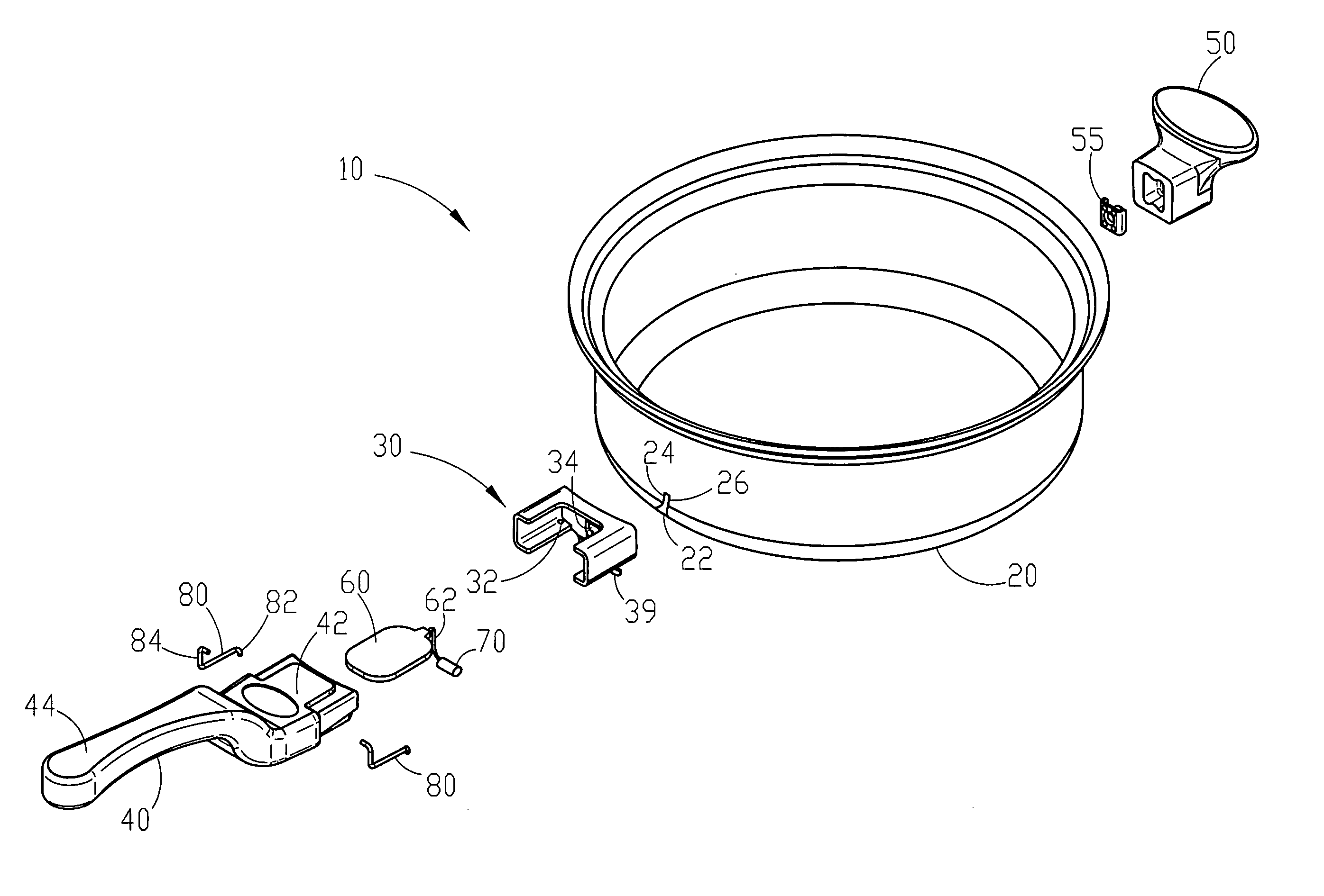
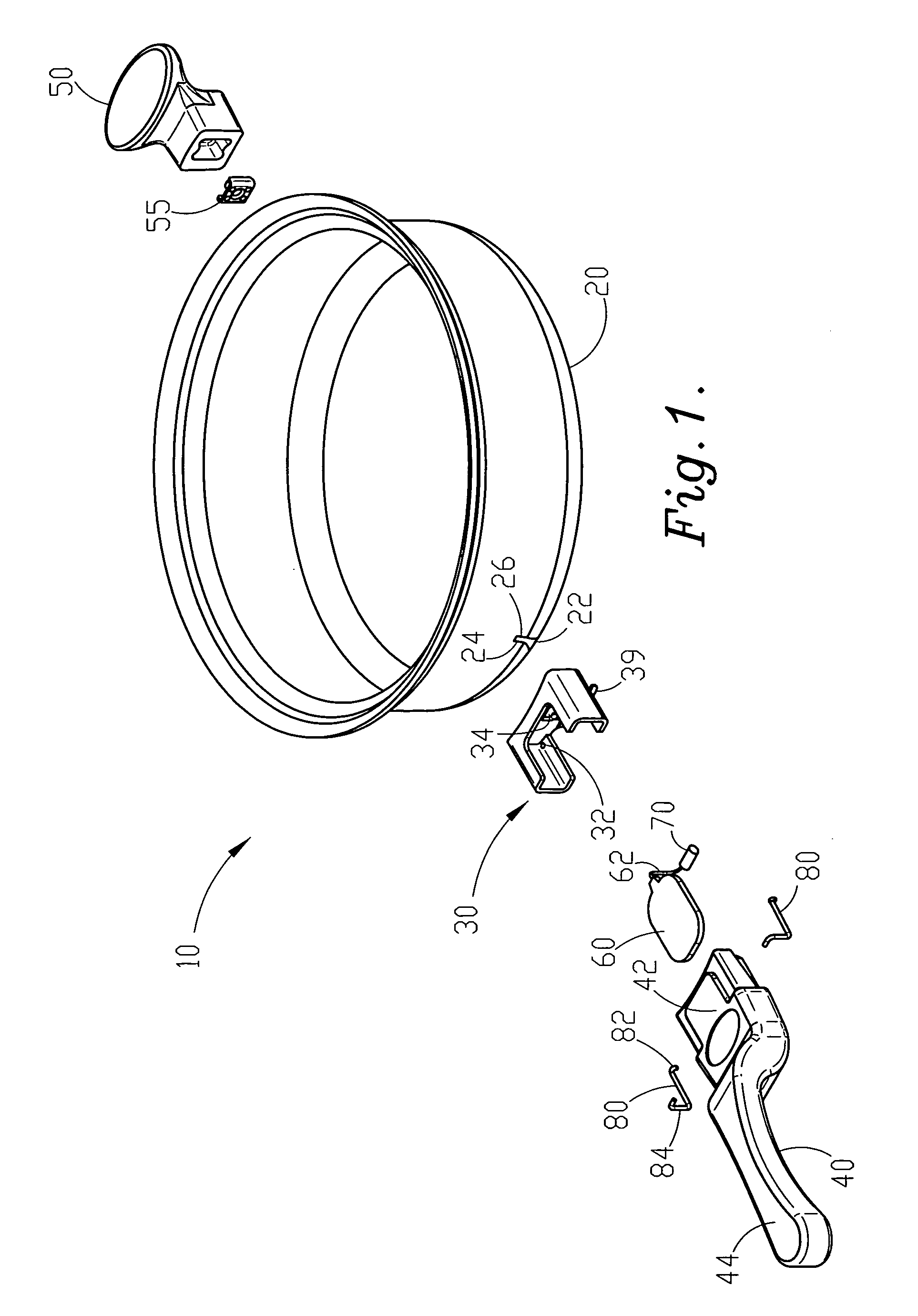
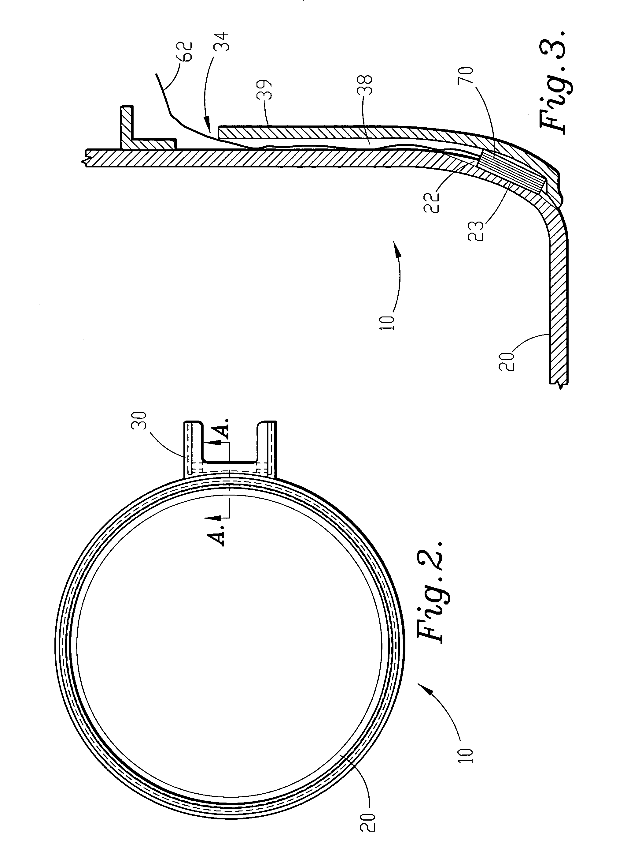
[0048]Referring to FIGS. 1 through 3, an RFID controlled cookware object, in the form of a frying pan is shown. FIG. 1 shows an exploded view of cookware object 10 including pan body 20, primary handle 40, and secondary (helper) handle 50. Primary handle 40 is connected to pan body 20 via bracket / receiver 30. Spring clips 80 releasably secure primary handle 40 to receiver 30 through the engagement of clip ends 82 with holes 32 in receiver 30. Helper handle 50 is connected to pan body 20 via bracket 55. An RFID tag, 60, is connected to temperature sensor 70 via a pair of wires, 72. RFID tag 60 is stored in a cavity located within handle 40. Wires 72 extend from the interior of the cavity through a portal 34 of receiver 30 to sensor 70 which is generally located between receiver 30 and the exterior of pan body 20 within notch 22 formed into the side of pan body 20.

[0049]Pan body 20 is fabricated from materials and manufactured by means well known in the art. Types of materials commonl...

second embodiment

[0071]FIGS. 19 through 23 show several variations of pan 210 having a slab attached to the bottom of pan body 220, in which slot 222 is formed in slab 226 instead of being milled in pan body 220. Locating slot 222 within slab 226 allows for a thinner wall thickness for pan body 220, and eliminates the need to perform any machining operations on pan body 220 once the body is manufactured (other than braising slab 226 to pan body 220). In a preferred embodiment of the slab base pan having a slot formed within the slab, slab 226 is constructed of an aluminum layer (or aluminum alloy) and a steel layer (although any other suitable material can be utilized for slab 226 depending upon the conductive, inductive and various other properties desired). Slot 222 is formed in the aluminum layer to position temperature sensor 70 in contact with the heat conductive aluminum to provide a more accurate temperature reading. The steel layer is positioned opposite the side of slab 226 that contacts pa...


PUM


Abstract

A temperature controlled heatable object is provided in which a temperature sensor is connected to a Radio Frequency Identification (RFID) tag. The RFID tag is located within the handle of the object, and the temperature sensor is placed in contact with the object. In a first embodiment of the invention, the temperature sensor is partially imbedded within the object via a notch located in the side of the object. In a second embodiment of the invention, a temperature sensor is imbedded within a tunnel drilled within the base of the object. In a third embodiment, a temperature sensor is imbedded between the bottom of the object and a slab attached to the bottom of the object. The sensor can be located in a slot formed in either the slab or the bottom or the object. Handles and receivers for mounting the handles to the temperature controllable objects are also provided.

Description

FIELD OF THE INVENTION[0001]The present invention is broadly concerned with temperature regulated cookware and servingware items, such as pots, pans, buffet serving pans, serving dishes, platters, and the like. More particularly, the invention is concerned with cookware and servingware objects that are temperature regulated using Radio Frequency Identification (RFID) technology and temperature sensors associated with the objects. An RFID tag, which is associated with a temperature sensor, includes information regarding heating characteristics of the particular object. The RFID tag transmits the information regarding the heating characteristics of the object as well as temperature reading information to a reader located within a cookware appliance, which are used by the cookware appliance to regulate the temperature of the cooking process.BACKGROUND OF THE INVENTION[0002]Cooking is often referred to as an art, not only because of the combination of ingredients that go into a particul...

Claims


Application Information

Patent Timeline
Patent Type & Authority Patents(United States)
IPC IPC(8): H05B6/12H05B7/02A47J27/00A47J27/62A47J45/06A47J45/07H04B1/59H04B5/02H05B1/02
CPCA47J27/62A47J45/068A47J45/071H05B6/12A47J36/00H05B1/0266H05B1/0269A47J45/07H05B2213/06A47J36/321H04B5/0062G06K7/10336G06K19/0717H05B6/101
Inventor IMURA, MAMORU
Owner IMURA INT USA
Why Eureka
Try Eureka