
System and method for shadow rendering

a shadow rendering and shadow technology, applied in the field of video graphics rendering, can solve the problems of multiple passes, high overhead and time delay, and achieve the effect of latency and needed storage capacity

Inactive Publication Date: 2007-01-02
S3 GRAPHICS
View PDF17 Cites 3 Cited by
  • Summary
  • Abstract
  • Description
  • Claims
  • Application Information

AI Technical Summary

Benefits of technology

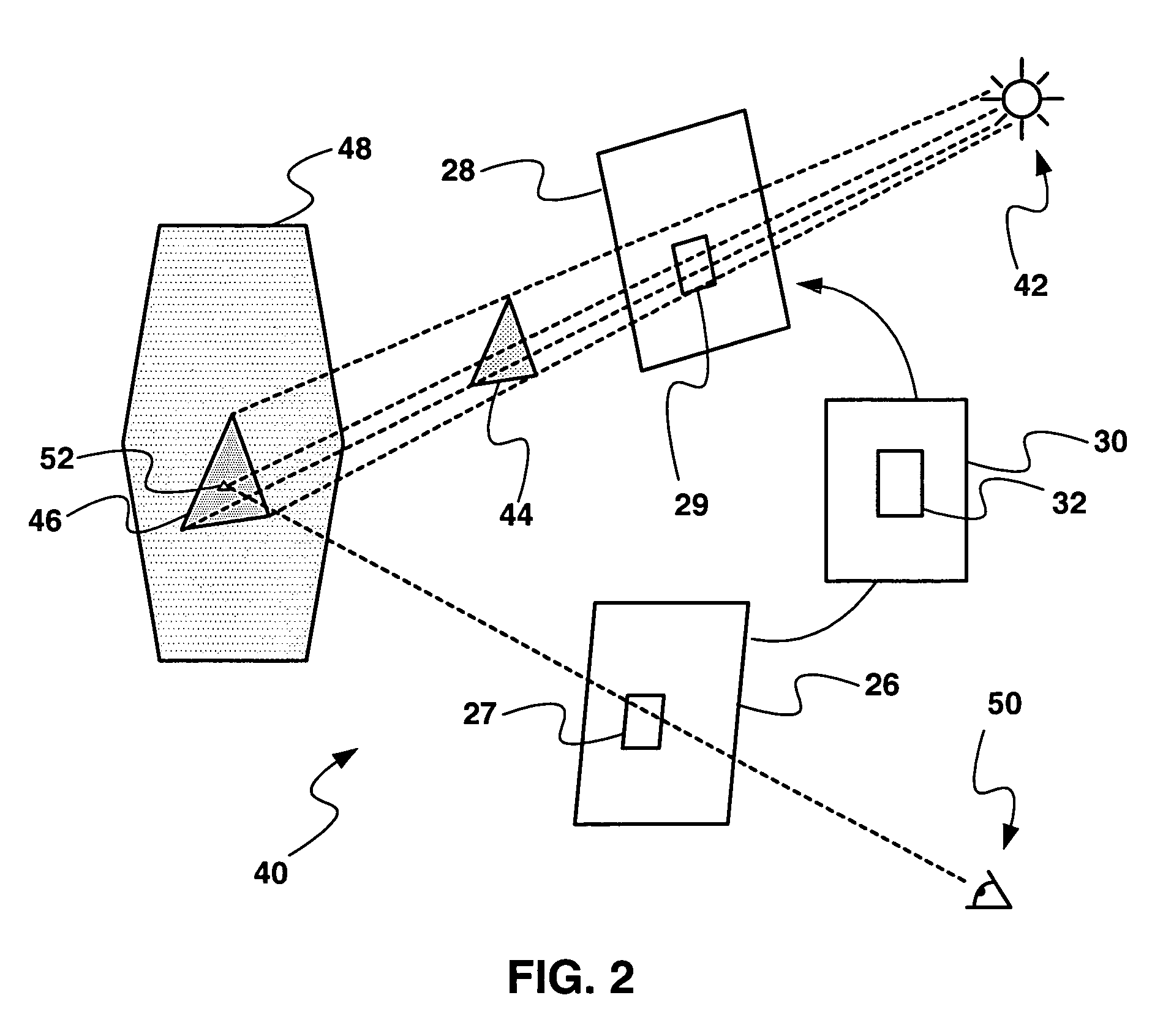
[0016]The present invention provides a system and method in which three-dimensional (3D) objects are processed only once and the rendering and shadow generation information is stored in memory. In a two-dimensional (2D) pass, the shadow information is used to modulate the color value at each rendered pixel. Thus, the latency and needed storage capacity due to the multiple 3D pass processing is eliminated.
[0018]This greatly reduces the overall processing time by eliminating processing steps.

Problems solved by technology

The basic difficulty in achieving total visual realism is the complexity of quickly and accurately representing real world visual effects.
This shadow algorithm can cause self-shadowing artifacts because only a single Z value is stored for each element in the shadow depth map.
Another problem which arises in Z-buffer techniques is caused by “aliasing” in the shadow depth map.
The multiple passes introduce a great deal of overhead and time delay, or latency, in the graphic pipeline.

Method used


Image

  • System and method for shadow rendering
  • System and method for shadow rendering
  • System and method for shadow rendering

Examples


Embodiment Construction

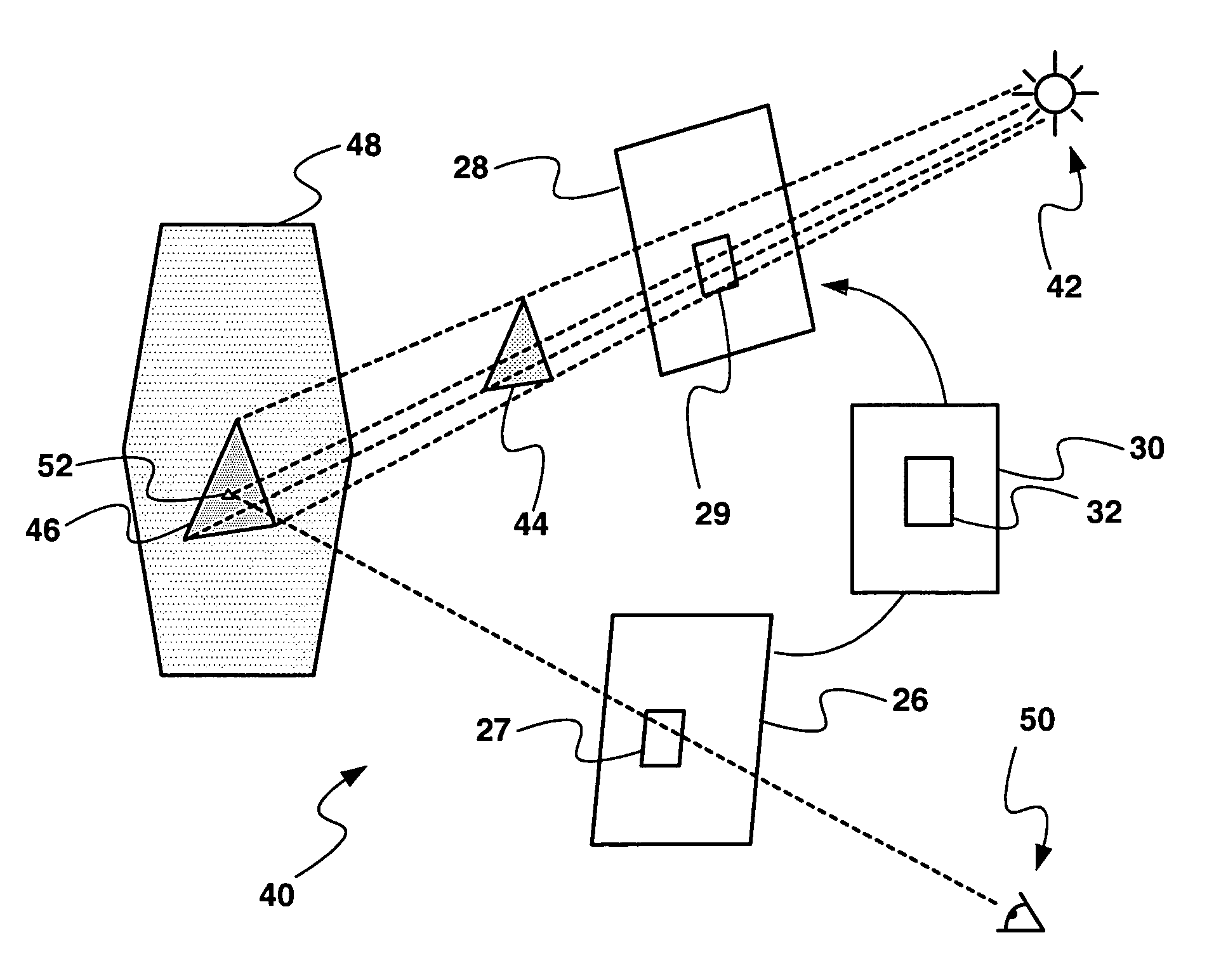
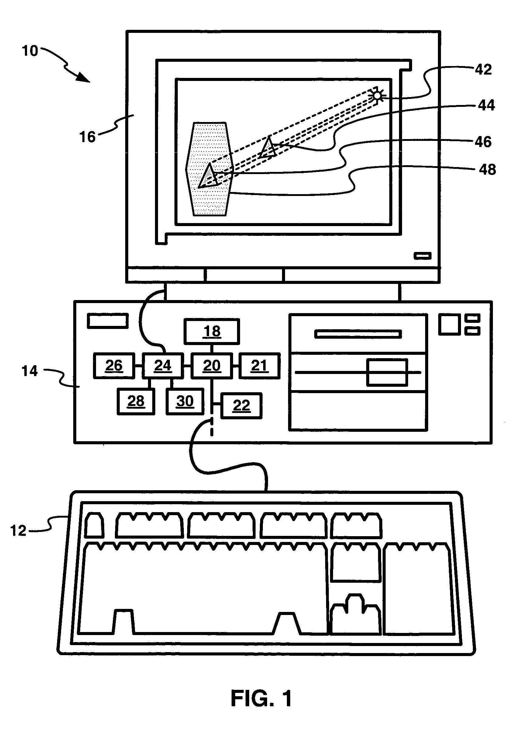
[0022]Referring now to FIG. 1, therein is shown a computing system 10 which includes an input device 12, a computing device 14, and an output display 16. The computing device 14 contains all the conventional components for operation of the computing system 10, including a central processing unit (CPU) 18. The CPU 18 performs most of the computation operations of the computing device 14 except those related to the output display 16. The CPU 18 is connected to a north bridge chip 20, which in turn is connected to a south bridge chip 22. The north bridge chip 20 is an interconnection chip to memory 21 and to a graphics chip 24. The south bridge chip 22 contains peripheral components related circuitry.

[0023]The graphics chip 24 is a graphics coprocessor which performs calculations necessary for high quality, high speed graphics, such as that used in 3D games. The graphics chip 24 comprises a frame buffer 26, a shadow buffer 28, and memory 30 operatively associated with it although in so...


PUM


Abstract

A system and method for providing shadow information for 3D computer graphics objects on a display for a graphic computer system are disclosed. The 3D objects are processed only once and the rendering and shadow generation information is stored in memory. In a subsequent two-dimensional pass, the shadow information is used to provide the color value at each rendered pixel. Thus, the latency and the need for storage capacity due to the multiple 3D pass processing are eliminated.

Description

CROSS REFERENCE TO RELATED APPLICATIONS[0001]This application is a continuation and claims the priority benefit of U.S. patent application Ser. No.09 / 664,283 filed Sep. 18, 2000 and entitled “Shadow Rendering System end Method” now U.S. Pat. No. 6,791,544; U.S. patent application Ser. No. 09 / 664,283 claims the benefit of U.S. provisional patent application No. 60 / 195,230 filed on Apr. 6, 2000. The disclosure of both of these applications is incorporated herein by reference.BACKGROUND OF THE INVENTION[0002]1. Field of the Invention[0003]The present invention relates generally to video graphics rendering, and more particularly to the rendering of shadows.[0004]2. Description of Related Art[0005]In video graphics rendering, it is important to produce images that are realistic on a real-time basis. The basic difficulty in achieving total visual realism is the complexity of quickly and accurately representing real world visual effects. A scene can include a variety of textures, color gra...

Claims


Application Information

Patent Timeline
Patent Type & Authority Patents(United States)
IPC IPC(8): G06T15/50G06T15/60
CPCG06T15/60
Inventor HONG, ZHOUIOURCHA, KONSTANTINE
Owner S3 GRAPHICS
Learn More