Cyclone separator

a cyclone separator and separator technology, applied in the direction of centrifuges, separation processes, vortex flow apparatus, etc., can solve the problems of insufficient cleaning action at lower volume flows, difficult to design a cyclone separator suitable for cleaning, and rapid movement of eddy to form

Inactive Publication Date: 2007-01-09
MANN HUMMEL GMBH
View PDF9 Cites 51 Cited by
  • Summary
  • Abstract
  • Description
  • Claims
  • Application Information

AI Technical Summary

Benefits of technology

[0005]It is an object of the present invention ...

Problems solved by technology

This causes a rapidly moving eddy to form.
However, it is difficult to design a cyclone separator suitable for cleaning gas streams across a broad range of volume flow rates.
If the cyclone separator is adapted to the maximum volume flow tha...

Method used


Image

  • Cyclone separator
  • Cyclone separator
  • Cyclone separator

Examples


Embodiment Construction

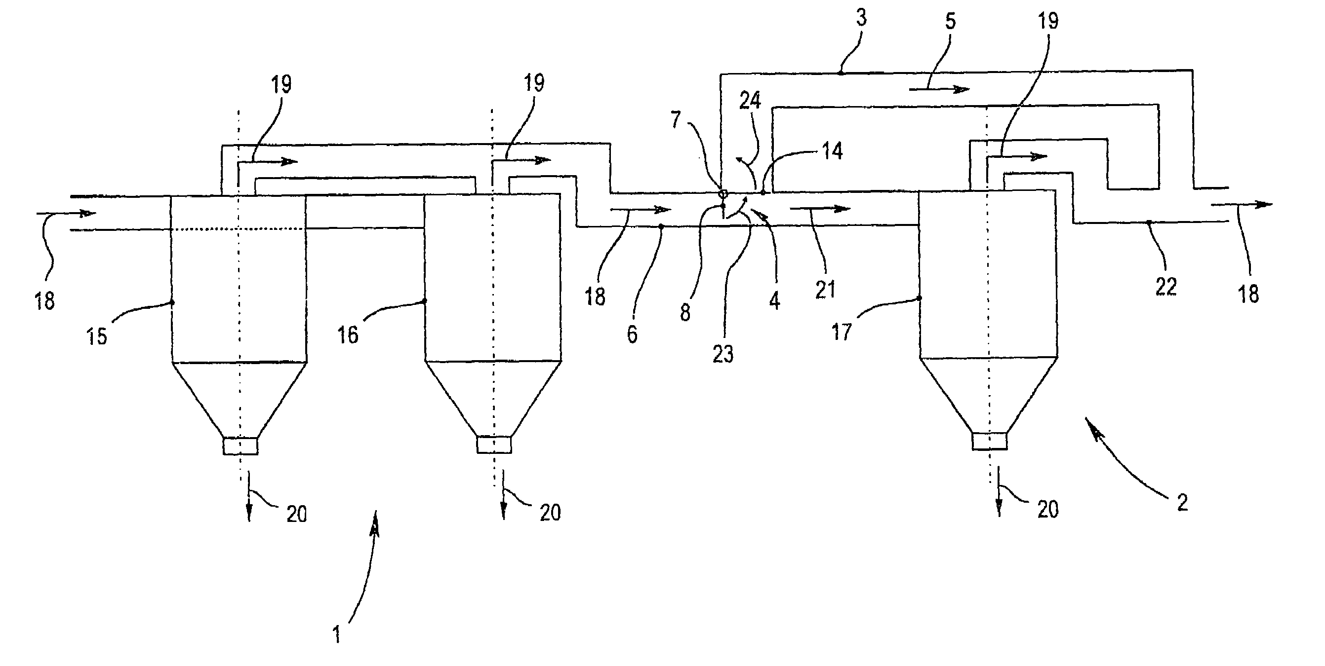
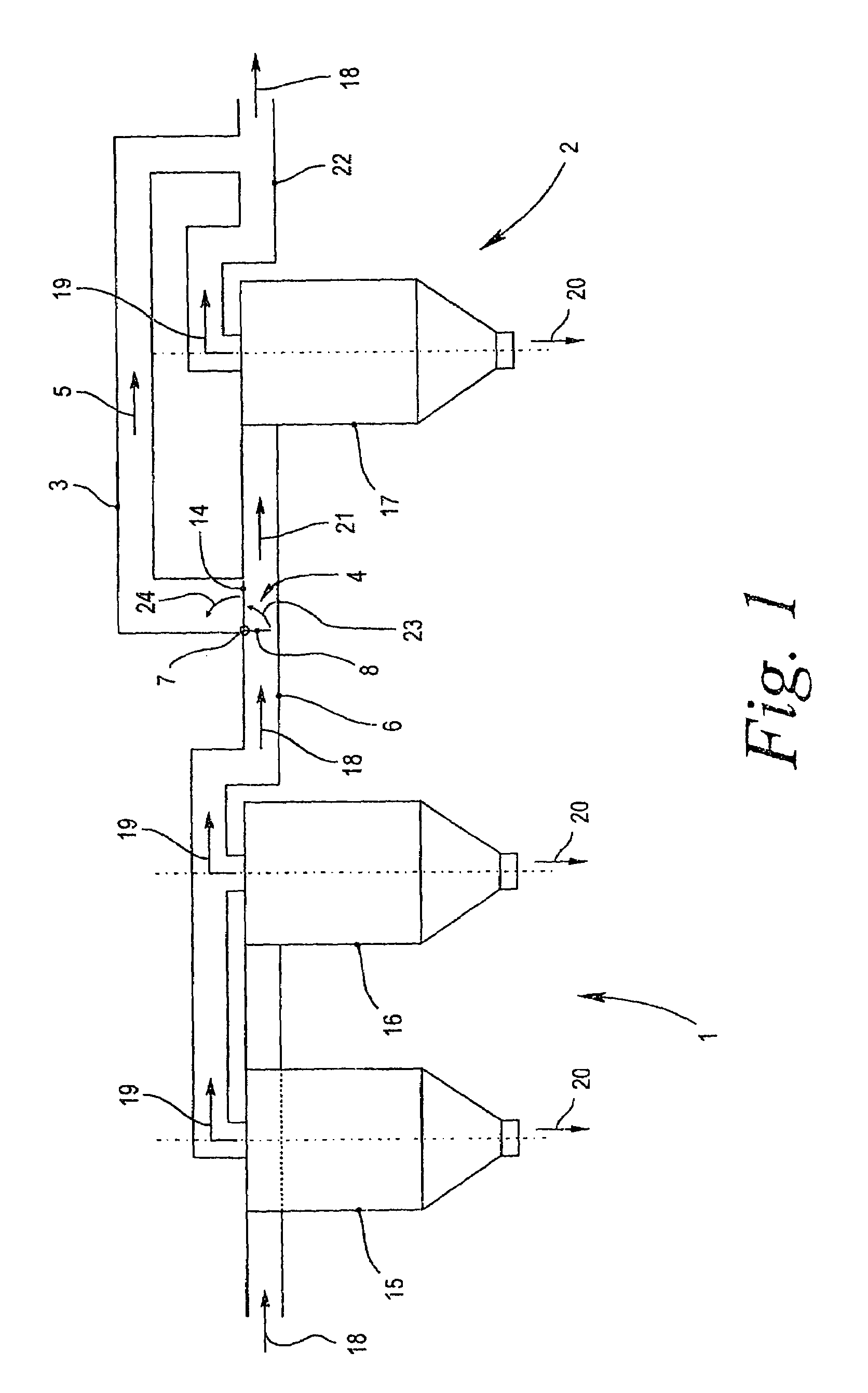
[0024]FIG. 1 is a schematic of a cyclone separator with a first cyclone arrangement 1 and a second cyclone arrangement 2. The gas flows through the cyclone arrangement 1 in the flow direction indicated by arrows 18. In relation to the flow direction 18, the second cyclone arrangement 2 is connected in series to the first cyclone arrangement 1.

[0025]A total of three cyclones 15, 16, 17 having approximately the same configuration are provided. The initial cyclone arrangement 1 includes the two cyclones 15, 16, which are connected in parallel. The second cyclone arrangement 2 includes only a single cyclone 17. It may also be advantageous to provide the cyclone arrangements 1 and 2 with only a single cyclone each or with any other number of cyclones 15, 16, 17. The cyclones 15, 16, 17 can also differ from one another with respect to their size and configuration.

[0026]The gas stream with the entrained impurities flows into the area of the initial cyclone arrangement on the inflow side an...


PUM

PropertyMeasurementUnit
Areaaaaaaaaaaa

Abstract

A cyclone separator including an initial cyclone arrangement (1) arranged first in relation to a flow direction (18) through the separator; a second cyclone arrangement (2) connected in series with the initial cyclone arrangement; a bypass channel (3) bypassing the second cyclone arrangement (2), and a volumetric flow controlled valve device (4) for selectively directing a partial stream (5) through the bypass channel (3).

Description

BACKGROUND OF THE INVENTION[0001]The invention relates to a cyclone separator comprising first and second cyclone arrangements connected in series.[0002]Cyclone separators having a known type of construction are used in many devices for removing impurities from a gas stream. Such impurities can be dust particles, droplets of a liquid or the like. In particular, it is well known to arrange a cyclone separator in a crankcase ventilation system of an internal combustion engine. So-called blow-by gases are conveyed via the crankcase ventilation system to the air intake tract of the internal combustion engine. It is desirable to remove oil droplets entrained in the gas stream as completely as possible.[0003]To separate entrained contaminants, the gas stream is directed approximately tangentially into a cyclone with an approximately round cross section. This causes a rapidly moving eddy to form. The centrifugal forces acting on the entrained contaminants cause these impurities to be depos...

Claims


Application Information

Patent Timeline
IPC IPC(8): B04B5/10B01D45/12B04C5/26F01M13/04
CPCB01D45/12B04C5/26F01M2013/0427
Inventor HILPERT, TORSTENTRAUTMANN, PIUS
Owner MANN HUMMEL GMBH
Why Eureka
Try Eureka