Axially compressible artificial intervertebral disc having limited rotation using a captured ball and socket joint with a solid ball and compression locking post

a technology of compressed artificial discs and solid balls, which is applied in the field of spinal implant assemblies, can solve the problems of collateral injury to the patient's spine, restricting the overall flexibility of the spinal column, and constraining the normal motion of the patient, so as to prevent the translation and separation of the baseplates

Inactive Publication Date: 2007-01-09
HOWMEDICA OSTEONICS CORP
View PDF136 Cites 51 Cited by
  • Summary
  • Abstract
  • Description
  • Claims
  • Application Information

AI Technical Summary

Benefits of technology

[0061]Therefore, when assembled, these embodiments of the fourth embodiment family enable angulation and limited rotation of the baseplates relative to one another about a centroid of motion that remains centrally located between the baseplates (at the center of the sphere defined by the ball), similar to the centroid of motion in a healthy natural intervertebral disc that is limited in its rotation by surrounding body structures. A benefit of limiting the relative rotation of the baseplates is that relative rotation beyond a certain range in a healthy natural disc is neither needed nor desired, because, for example, excess strain can be placed on the facet joints or ligaments thereby. As described with the rotationally free embodiments of the third embodiment family, the construction also prevents translation and separation of the baseplates relative to one another during rotation and angulation.

Problems solved by technology

It is, however, important to note that the fusion of the adjacent bones is an incomplete solution to the underlying pathology as it does not cure the ailment, but rather simply masks the pathology under a stabilizing bridge of bone.
This bone fusion limits the overall flexibility of the spinal column and artificially constrains the normal motion of the patient.
This constraint can cause collateral injury to the patient's spine as additional stresses of motion, normally borne by the now-fused joint, are transferred onto the nearby facet joints and intervertebral discs.

Method used


Image

  • Axially compressible artificial intervertebral disc having limited rotation using a captured ball and socket joint with a solid ball and compression locking post
  • Axially compressible artificial intervertebral disc having limited rotation using a captured ball and socket joint with a solid ball and compression locking post
  • Axially compressible artificial intervertebral disc having limited rotation using a captured ball and socket joint with a solid ball and compression locking post

Examples


first embodiment

[0107]A preferred embodiment of a first embodiment family of the present invention will now be described.

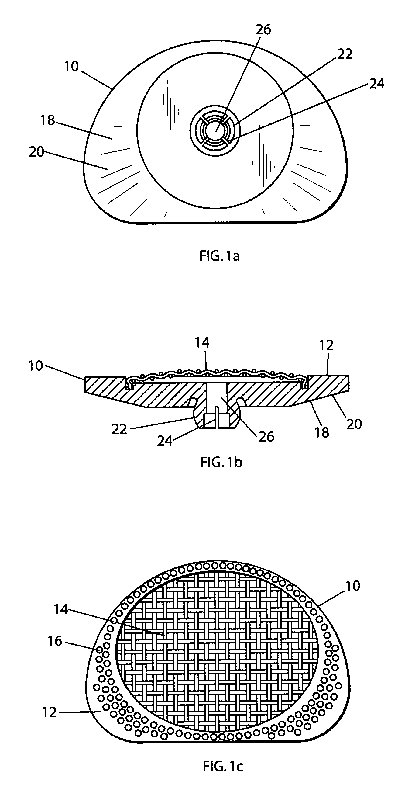
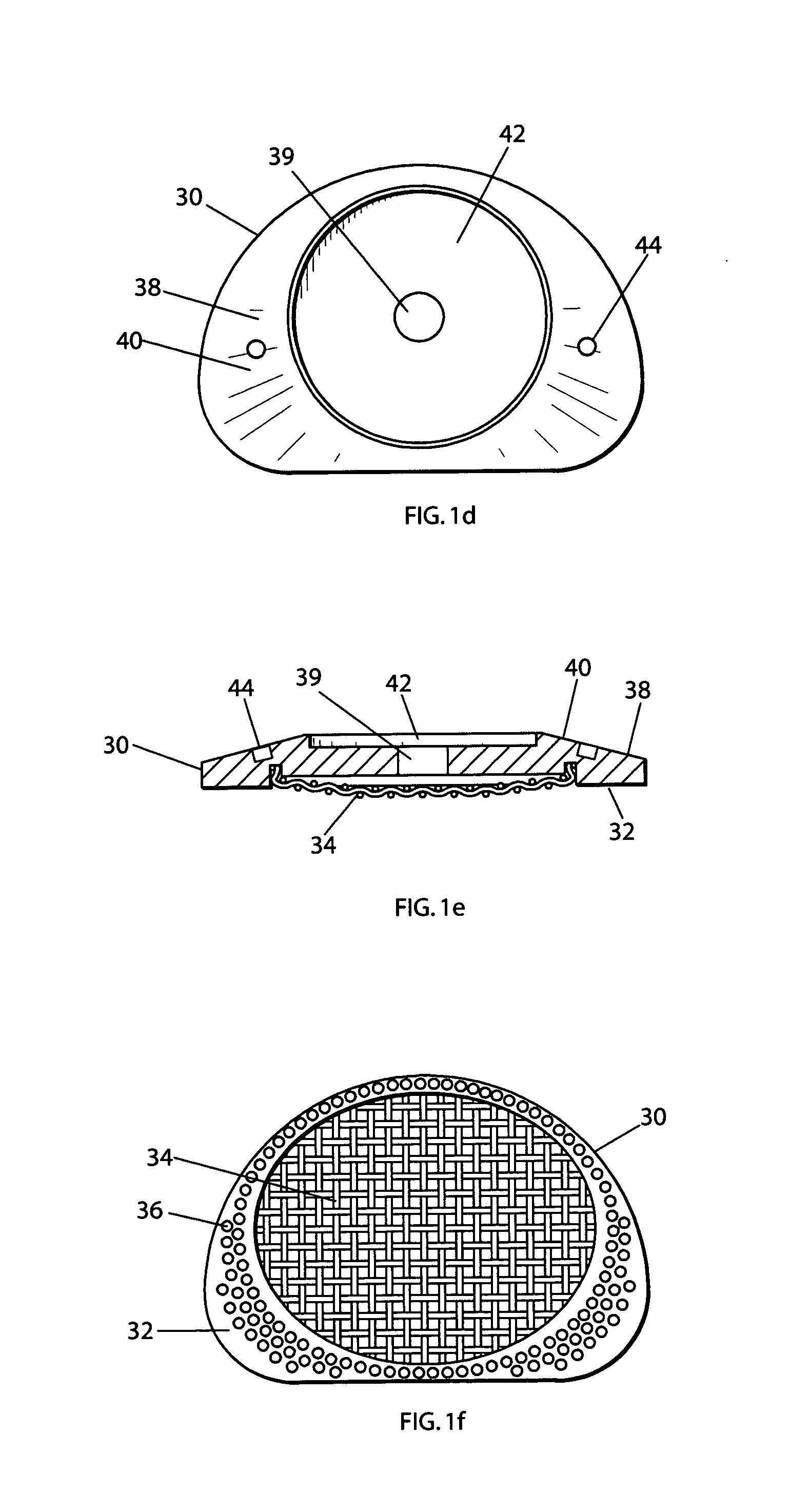
[0108]Referring to FIGS. 1a–c, a first baseplate 10 of a first embodiment family of the present invention is shown in top (FIG. 1a), side cutaway (FIG. 1b) and bottom (FIG. 1c) views. Also referring to FIGS. 1d–f, a second baseplate 30 of the first embodiment family is shown in top (FIG. 1d), side cutaway (FIG. 1e) and bottom (FIG. 1f) views.

[0109]More specifically, each baseplate 10,30 has an outwardly facing surface 12,32. Because the artificial disc of the invention is to be positioned between the facing surfaces of adjacent vertebral bodies, the two baseplates 10,30 used in the artificial disc are disposed such that the outwardly facing surfaces 12,32 face away from one another (as best seen in exploded view in FIG. 1g and in assembly view in FIG. 1h). The two baseplates 10,30 are to mate with the vertebral bodies so as to not rotate relative thereto, but rather to permit the...

second embodiment

[0126]A preferred embodiment of a second embodiment family of the present invention will now be described.

[0127]Referring to FIGS. 2a–c, a first baseplate 50 of a second embodiment family of the present invention is shown in top (FIG. 2a), side cutaway (FIG. 2b) and bottom (FIG. 2c) views. Also referring to FIGS. 2d–f, a second baseplate 70 of the second embodiment family is shown in top (FIG. 2d), side cutaway (FIG. 2e) and bottom (FIG. 2f) views.

[0128]With regard to the configuration of the convex structure in this second embodiment family, and the manner in which the ball is captured in the socket in this second embodiment family, the convex structure is configured as a non-flexible element that is integral with the second baseplate, and has the socket of the ball and socket joint at its peak. More clearly stated, the devices of this second embodiment family do not feature a flexible convex structure, and therefore (and also because of the manner in which the ball is captured in ...

third embodiment

[0133]Embodiments of the third embodiment family of the present invention will now be described.

[0134]With regard to the configuration of the convex structure in the third embodiment family, the convex structure is configured as a non-flexible element that is integral with the second baseplate, and has the socket of the ball and socket joint at its peak, similar to the configuration of the convex structure in the second embodiment family. In the preferred embodiment, the convex structure is shaped to have a curved taper.

[0135]With regard to the manner in which the ball is captured in the socket in the third embodiment family, the capturing is effected through the use of a solid ball. In order to permit the seating of the ball into the socket formed at the peak of the convex structure, the access hole in the second baseplate has a diameter that accommodates the diameter of the ball, and leads to the interior of the peak, which interior is formed as a concavity having an opening diame...


PUM

PropertyMeasurementUnit
compressiveaaaaaaaaaa
rotationaaaaaaaaaa
perimeteraaaaaaaaaa

Abstract

An artificial disc having a pair of opposing baseplates, for seating against opposing vertebral bone surfaces, separated by a ball and socket joint that includes a ball compression locked to a post extending from one of the baseplates. The ball is captured within a curvate socket formed in a peak of a convex structure attached to the other of the baseplates. The socket is formed by opposing curvate surfaces, one on the convex structure and one on the other of the baseplates. While the ball angulates freely in the socket, the rotation of the ball in the socket has a limited range due to interference between a protrusion on the convex structure that extends into the socket and a curvate recess on the ball. The ball and socket joint therefore permits the baseplates to rotate relative to one another through a limited range and also angulate relative to one another.

Description

CROSS REFERENCE TO RELATED APPLICATIONS[0001]The present application is a continuation-in-part application of U.S. patent application Ser. No. 10 / 256,160 (filed Sep. 26, 2002) entitled “Artificial Intervertebral Disc”, which is a continuation-in-part application of U.S. patent application Ser. No. 10 / 175,417 (filed Jun. 19, 2002) entitled “Artificial Intervertebral Disc Utilizing a Ball Joint Coupling”, which is a continuation-in-part application of U.S. patent application Ser. No. 10 / 151,280 (filed May 20, 2002) entitled “Tension Bearing Artificial Disc Providing a Centroid of Motion Centrally Located Within an Intervertebral Space”, which is a continuation-in-part application of both U.S. patent application Ser. No. 09 / 970,479 (filed Oct. 4, 2001) entitled “Intervertebral Spacer Device Utilizing a Spirally Slotted Belleville Washer Having Radially Extending Grooves,” now U.S. Pat. No. 6,669,730 as well as U.S. patent application Ser. No. 10 / 140,153 (filed May 7, 2002) entitled “Ar...

Claims


Application Information

Patent Timeline
Patent Type & Authority Patents(United States)
IPC IPC(8): A61F2/44A61B17/56A61F2/00A61F2/02A61F2/30A61F2/46
CPCA61F2/442A61F2/4425A61F2/446A61F2/4611A61F2/4684A61F2/30742A61F2310/00365A61F2002/30171A61F2002/30187A61F2002/302A61F2002/30331A61F2002/30365A61F2002/30378A61F2002/30433A61F2002/30441A61F2002/30443A61F2002/30444A61F2002/30446A61F2002/30451A61F2002/30454A61F2002/30492A61F2002/30502A61F2002/30507A61F2002/30518A61F2002/30528A61F2002/30538A61F2002/30563A61F2002/30565A61F2002/30571A61F2002/30594A61F2002/30604A61F2002/30649A61F2002/30662A61F2002/30769A61F2002/30772A61F2002/30774A61F2002/30841A61F2002/30909A61F2002/3092A61F2002/30975A61F2002/443A61F2220/0025A61F2220/0033A61F2220/0041A61F2220/0058A61F2230/0034A61F2230/005A61F2230/0065A61F2250/0006A61F2310/00017A61F2310/00023A61F2/30767A61F2002/305
Inventor ERRICO, JOSEPH P.DUDASIK, MICHAEL W.ZUBOK, RAFAIL
Owner HOWMEDICA OSTEONICS CORP
Why Eureka
Try Eureka