

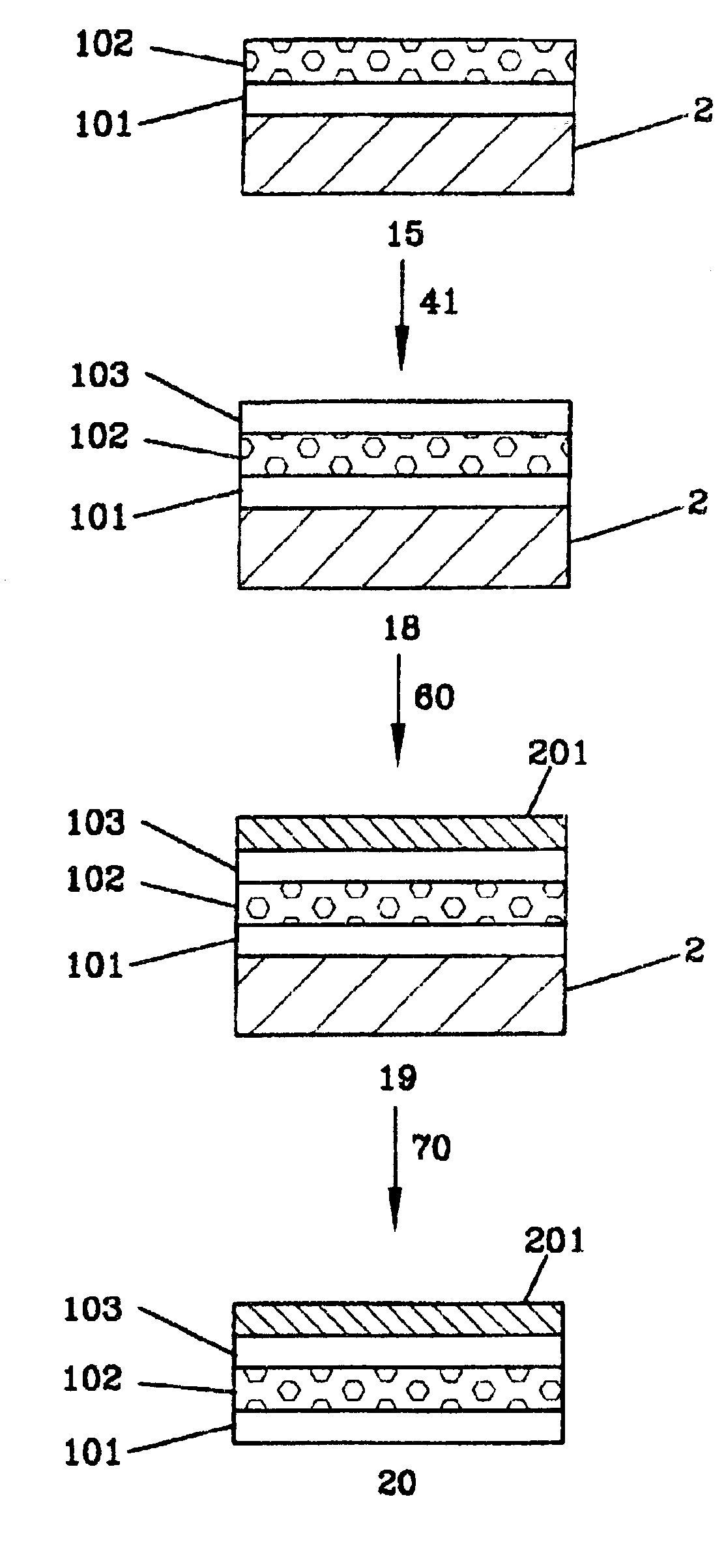
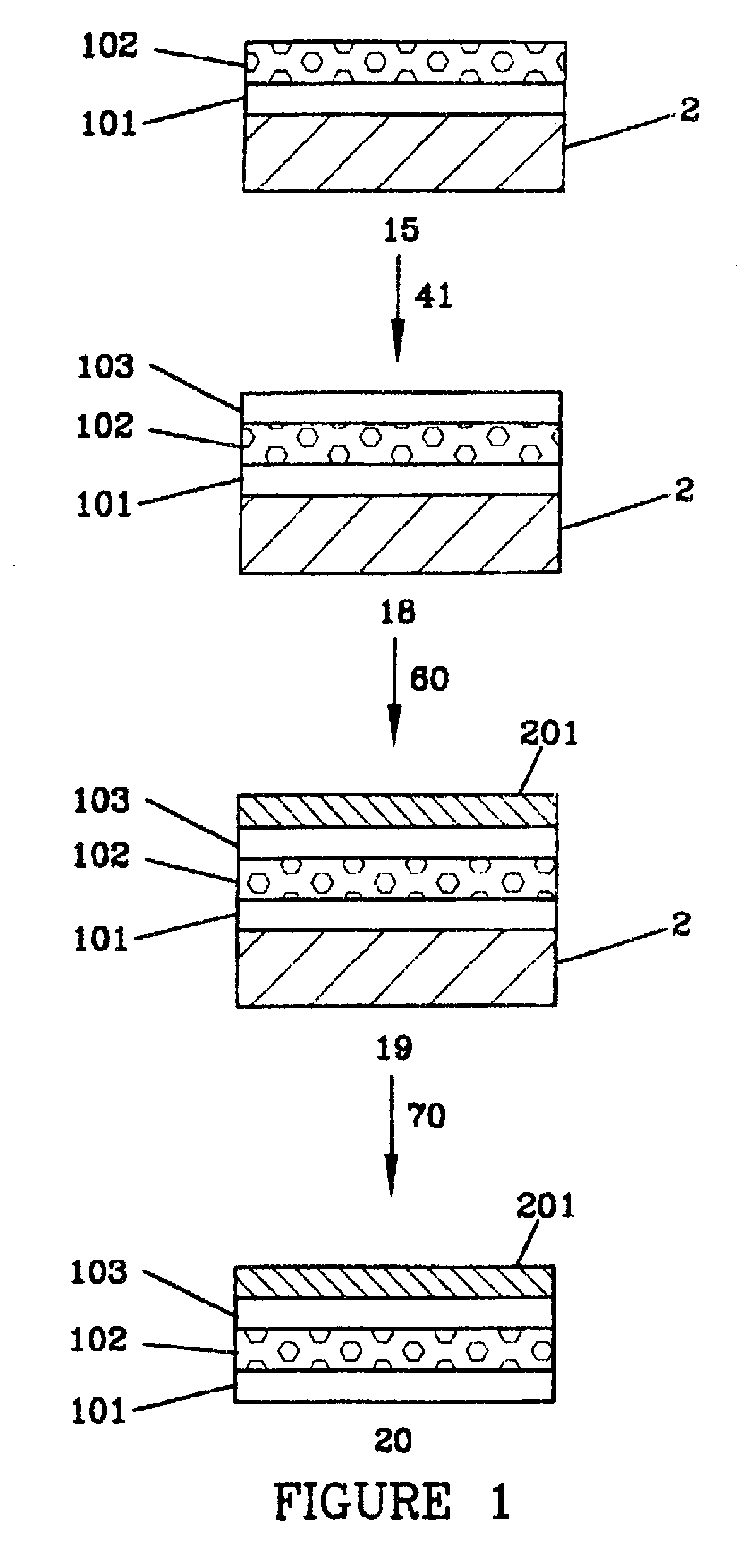
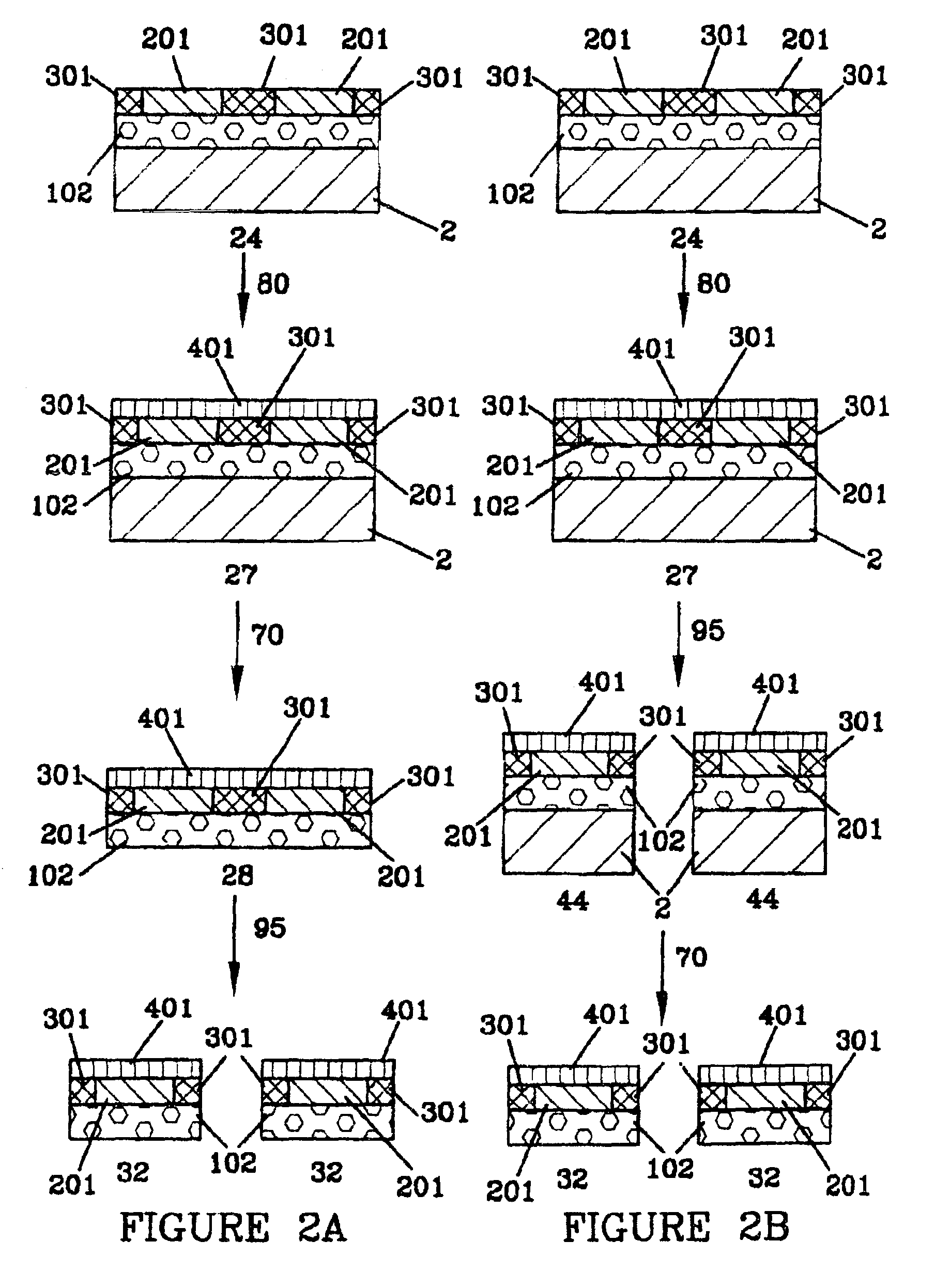
Microporous articles and methods of preparation
a microporous layer and microporous technology, applied in the direction of cell electrodes, fuel cells, cell component details, etc., can solve the problems of difficult coating, rough and non-uniform surfaces, and reduced surface roughness and non-uniformities
- Summary
- Abstract
- Description
- Claims
- Application Information
AI Technical Summary
Benefits of technology
Problems solved by technology
Method used
Image

Examples
example 1
[0057]A coating mixture for a microporous ink jet ink-receptive layer was prepared by adding 23.8 g of a 13.5% by weight solids solution of boehmite sol in water (DISPAL 11N7-12, a trademark for aluminum boehmite sols available from CONDEA Vista company, Houston, Tex.) to 14.2 g of a 4% by weight solution of polyvinyl alcohol (AIRVOL 125, a trademark for polyvinyl alcohol polymers available from Air Products, Inc. Allentown, Pa.) in water and stirring to mix the materials. 0.05 g of FLUORAD FC-430, a trademark for non-ionic fluorochemical surfactants available from 3M Corporation, St. Paul, Minn., was added with stirring to make the final microporous coating mix. Using a gap coating with a doctor blade and a hand coating process, the microporous coating mix was applied to the non-treated surface of 23 micron thick MELINEX 6328, a trademark for polyethylene terephthalate (PET) films available from DuPont Teijin Films, Wilmington, Del. After air drying in a laboratory hood under a hig...
PUM
| Property | Measurement | Unit |
|---|---|---|
| thickness | aaaaa | aaaaa |
| diameter | aaaaa | aaaaa |
| pore diameters | aaaaa | aaaaa |
Abstract
Description
Claims
Application Information