Plasma torch having a quick-connect retaining cup

a technology of quick-connecting and retaining cups, which is applied in the field of quick-connect retaining cups, can solve the problems of substantial heat generation, inoperability of the torch, and components of the consumable assembly being subjected to elevated temperatures during torch operation, and achieve the effect of quick and repeatable connection

Active Publication Date: 2007-01-09
ILLINOIS TOOL WORKS INC
View PDF5 Cites 35 Cited by
  • Summary
  • Abstract
  • Description
  • Claims
  • Application Information

AI Technical Summary

Benefits of technology

[0007]The present invention provides a plasma torch assembly that solves the aforementioned problems by providing a plasma torch assembly that includes a quick-connect retaining cup that is quickly and repeatably connectable to a plasma torch. The quick-connect retaining cup orients the consumable components to the plasma torch and assures proper alignment of the components therewith.
[0009]In accordance with another aspect of the present invention, a plasma cutter is disclosed that includes a power source configured to condition power into a form usable by a plasma cutting process. The plasma cutter also includes a torch connected to the power source and configured to effectuate the plasma cutting process. An electrode is disposed in the torch, and a cup having a twist-lock quick-connect mechanism removably connects the cup to the torch and is constructed to maintain an operable position of the electrode and prevent overtightening of the cup to the torch.

Problems solved by technology

Improper alignment of the components of the torch can result in premature wear of the components or, if unaddressed, can result in inoperability of the torch.
Additionally, as the arc transfers from the electrode to the workpiece in the plasma, substantial heat is generated.
Improper consumable alignment can result in the components of the consumable assembly being subjected to elevated temperatures during torch operation.
Cutting with an overheated or overused consumable can result in poor cut quality or reduced cutting speeds.
As such, operating life of the components of the consumable assembly is partly dependent on operating conditions and, if unaddressed, may require replacement of the consumable assembly in the middle of a cutting job.
After extended periods of operation, the electrode, cup, and other consumables can become worn.
Replacing threaded components consumes time from the cutting process and reduces efficiency.
Also, overtightening or cross-threading of the cap during replacement of the tip and electrode can result in improper alignment of the components within the torch.
Such misalignments can detract from cut quality, increase component wear, and can ultimately result in torch inoperability—requiring total replacement.

Method used


Image

  • Plasma torch having a quick-connect retaining cup
  • Plasma torch having a quick-connect retaining cup
  • Plasma torch having a quick-connect retaining cup

Examples


Embodiment Construction

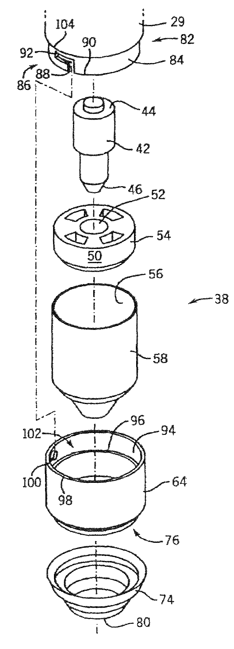
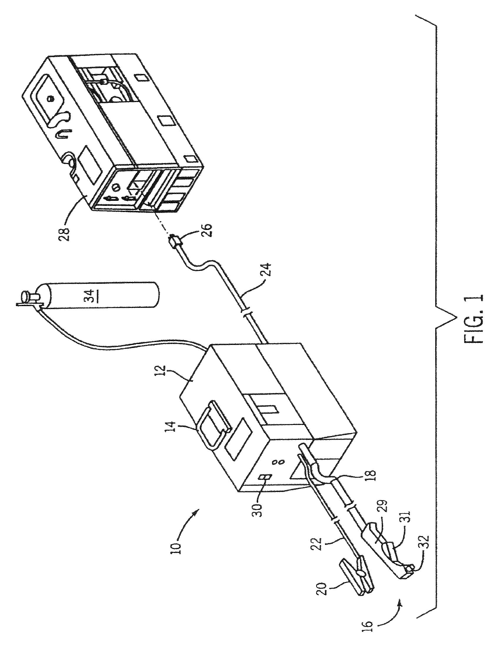
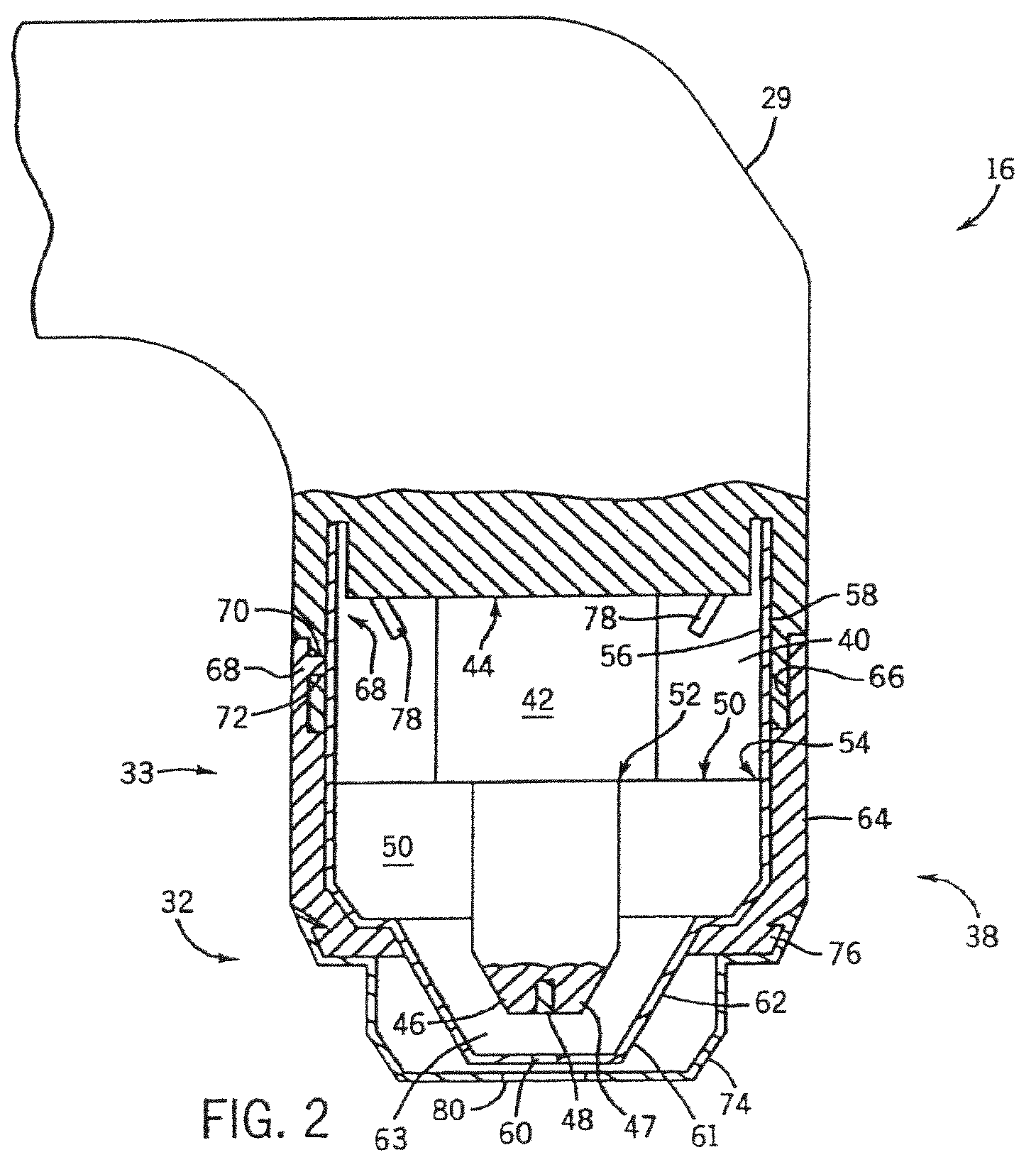
[0018]FIG. 1 shows a plasma cutting system 10 according to the present invention. The plasma cutting system is a high voltage system with open circuit output voltages ranging from approximately 230 Volts Direct Current (VDC) to over 300 VDC. The plasma cutting system 10 includes a power source 12 to condition raw power and regulate / control the cutting process. Specifically, the power source 12 includes a processor that receives operational feedback and controls the plasma cutting system 10 accordingly. Power source 12 includes a lifting means 14, such as a handle, which effectuates transportation from one site to another. Connected to the power source 12 is a torch 16 via cable 18. The cable 18 provides the torch 16 with power and compressed air, and also serves as a communications link between the torch 16 and power source 12. Torch 16 includes a handle portion, or torch body 29 having a trigger 31 thereon and work tip 32 extending therefrom.

[0019]Also connected to power source 12 ...


PUM

PropertyMeasurementUnit
rotationaaaaaaaaaa
degrees of rotationaaaaaaaaaa
rotationaaaaaaaaaa

Abstract

A plasma torch assembly having a quick-connect retaining cup is disclosed. The plasma torch has a torch body constructed to receive an electrode therein. A retaining cup secures the electrode to the torch body by rotating the retaining cup less than approximately 360 degrees relative to the torch body.

Description

BACKGROUND OF INVENTION[0001]The present invention relates generally to plasma cutting systems and other high power output welding-type systems such as welding and induction heating systems and, more particularly, to a quick-connect retaining cup for use with such systems.[0002]Plasma cutting is a process in which an electric arc is used for cutting a workpiece. Plasma cutters typically include a power source, an air supply, and a torch. The torch, or plasma torch, is used to create and maintain the plasma arc that performs the cutting. A plasma cutting power source receives an input voltage from a transmission power line or generator and provides output power to a pair of output terminals, one of which is connected to an electrode and the other of which is connected to the workpiece.[0003]An air supply is used with most plasma cutters to help start the arc, provide the plasma gas to the torch, and cool the torch. A movable or fixed electrode or consumable serves as a cathode and a ...

Claims


Application Information

Patent Timeline
Patent Type & Authority Patents(United States)
IPC IPC(8): B23K10/00
CPCH05H1/34H05H2001/3457H05H1/3457
Inventor SCHNEIDER, JOSEPH C.
Owner ILLINOIS TOOL WORKS INC
Why Eureka
Try Eureka