
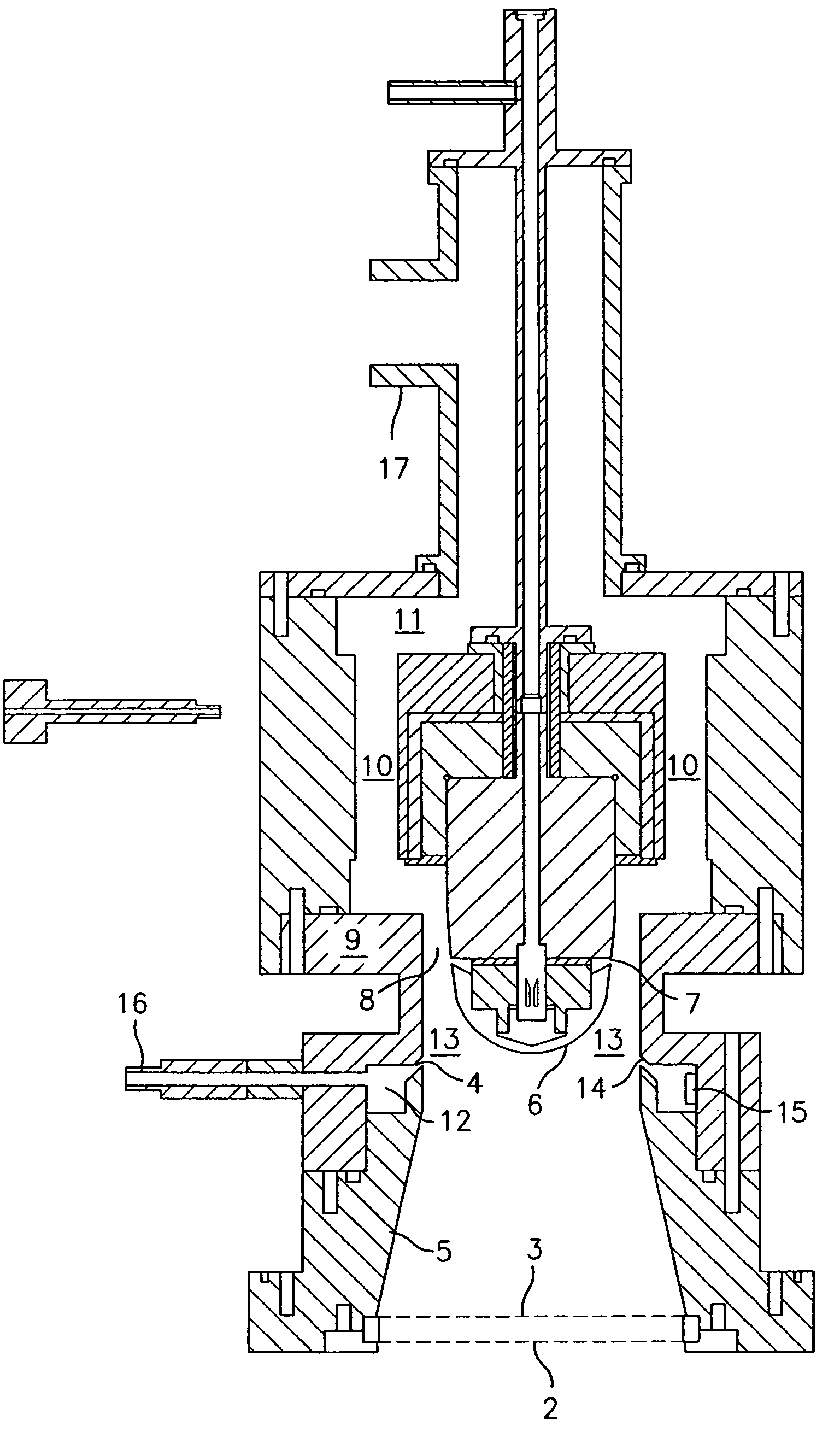
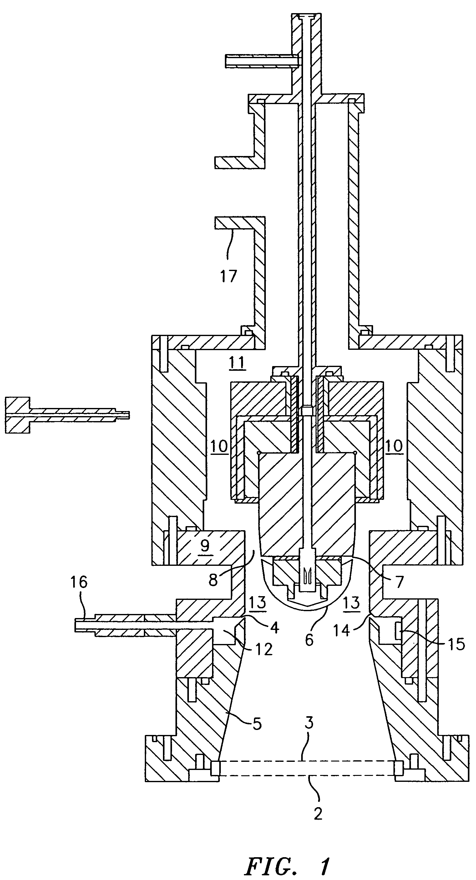
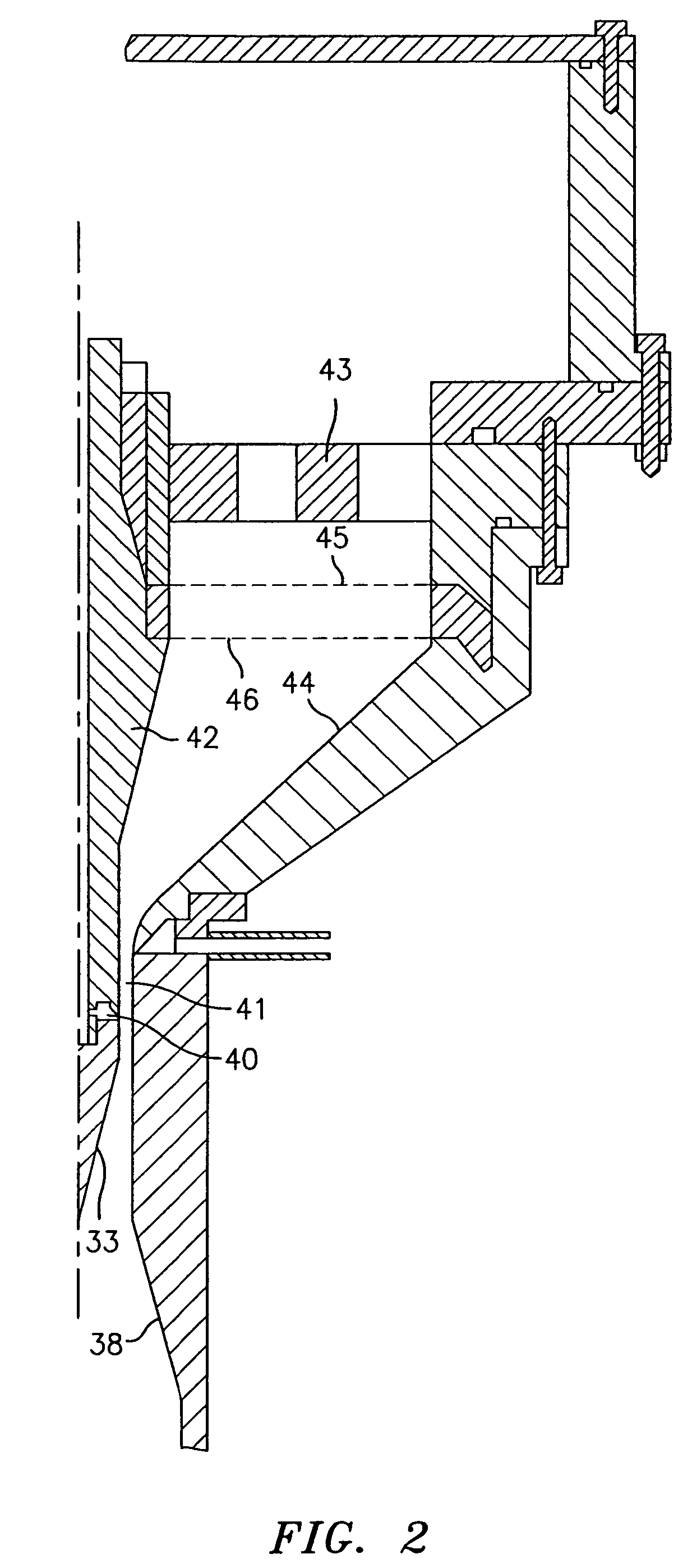
Method and apparatus to increase the resolution and widen the range of differential mobility analyzers (DMAs)

a technology of differential mobility analyzer and resolution, which is applied in the field of method and apparatus for sizing and classifying charged particles or ions in differential mobility analyzer, can solve the problems of brownian motion, difficult to achieve the desired range of reynolds, and difficult to apply practical exploitation of this knowledge, so as to minimize pressure drop

Inactive Publication Date: 2007-01-09
DE LA MORA JUAN FERNANDEZ +3
View PDF3 Cites 12 Cited by
  • Summary
  • Abstract
  • Description
  • Claims
  • Application Information

AI Technical Summary

Benefits of technology

"The present invention is a method and apparatus for separating charged particles or ions in a differential mobility analyzer. The apparatus includes a means to provide a laminar flow of ion-free sheath gas, means to introduce ions and charged particles into the analyzing region, at least two electrodes charged to suitable potentials to create an electric field within the analyzing region, and a sampling or collecting device to sample or collect ions of a desired mobility. The method involves introducing a stream of charged particles or ions into the analyzing region, maintaining a laminar flow of a particle-free sheath gas, providing an electrical field in the analyzing region, and sampling or collecting ions of a desired mobility through the at least one collector device. The technical effect of the invention is to provide a reliable and efficient means for separating charged particles or ions in a differential mobility analyzer."

Problems solved by technology

The main obstacle limiting DMA resolution in the nanometer diameter range is Brownian motion.
However, the practical exploitation of this knowledge is made difficult by the natural tendency of high Reynolds number flows to become turbulent, as well as by the difficulties associated to the generation of the rather large flows required.
Under such conditions it would have been rather difficult to attain the desired range of Reynolds numbers up to 105.
Furthermore, even in the most carefully prepared laminarizing system, it is very difficult to avoid all external sources of velocity fluctuations.
And even when the fluctuation level of the entering flow is very small, local perturbations will tend to appear in the unstable mixing layer following the aerosol inlet.
However, this feature is meant to stabilize flows at Reynolds numbers well below 2000, and is likely to be ineffective at Re=105.

Method used


Image

  • Method and apparatus to increase the resolution and widen the range of differential mobility analyzers (DMAs)
  • Method and apparatus to increase the resolution and widen the range of differential mobility analyzers (DMAs)
  • Method and apparatus to increase the resolution and widen the range of differential mobility analyzers (DMAs)

Examples


Embodiment Construction

[0029]The instant invention comprises a method to keep the flow laminar at Reynolds numbers (Re) well above 35,000, the maximum value at which a carefully prepared DMA flow (with a large inlet trumpet) between cylinders or parallel plates has been previously seen to remain laminar. The new method stabilizes the flow by accelerating it. This feature is discussed in de la Mora, de la Mora, Diffusion Broadening in Converging Mobility Analyzers, J. Aerosol Science, Vol. 33, pp. 411–437 (2002), the subject matter of which is herein incorporated by reference in its entirety.

[0030]Generally, the present invention enables for the first time the attainment of high Reynolds numbers in excess of 105 under laminar conditions, and, with the improvements discussed below, further enables the construction of DMAs capable of ΔZ / Z (based on the full peak width at half height, FWHH) values as small as 0.01, even for particles with diameters smaller than 2 nanometers.

[0031]Another aspect of this invent...


PUM

PropertyMeasurementUnit
velocityaaaaaaaaaa
diameteraaaaaaaaaa
diametersaaaaaaaaaa

Abstract

A differential mobility analyzer (DMA) for separating charged particles or ions suspended in a gas and a method of using the DMA for separating such particles. The invention includes various means for increasing the resolution of the DMA by stabilizing the laminar flow within the DMA and by allowing unusually large flow velocities.

Description

CROSS REFERENCE TO RELATED APPLICATION[0001]This application is a continuation of U.S. application Ser. No. 10 / 286,672, filed Nov. 1, 2002, now U.S. Pat No. 6,787,763, which claims the benefit of U.S. Provisional Application No. 60 / 324,143, filed Nov. 2, 2001.FIELD OF THE INVENTION[0002]The invention relates to a method and apparatus for sizing and classifying charged particle or ions in a differential mobility analyzer.BACKGROUND OF THE INVENTION[0003]Differential mobility analyzers (DMAs) are the most powerful instruments available for sizing and classifying particles, especially in the diameter range below 100 nanometers. The most common DMA design involves two concentric cylindrical electrodes. The commercial versions of various instruments have served rather well the aerosol community's for several decades. A number of cylindrical designs have been studied, with different ratios between the electrode radii R1 and R2 and the axial distance L between inlet and outer slits for the...

Claims


Application Information

Patent Timeline
Patent Type & Authority Patents(United States)
IPC IPC(8): H01J49/40G01N27/60G01N15/02G01N27/64
CPCG01N15/0266H01J49/40G01N2015/0288G01N27/623
Inventor DE LA MORA, JUAN FERNANDEZLABOWSKY, MICHAEL J.SCHMITT, III, JEROME J.NEILSON, G. WAYNE
Owner DE LA MORA JUAN FERNANDEZ
Learn More