
Vibrator support structure and manufacturing method for the support structure

a technology of vibration support and manufacturing method, which is applied in the direction of sustainable manufacturing/processing, instruments, final product manufacturing, etc., can solve the problems of easy stress on the support pin, increased number of parts, and complicated structur

Active Publication Date: 2007-01-09
MURATA MFG CO LTD
View PDF10 Cites 3 Cited by
  • Summary
  • Abstract
  • Description
  • Claims
  • Application Information

AI Technical Summary

Benefits of technology

The present invention provides a vibrator support structure and a method of manufacturing it that can effectively buffer vibrations and impacts propagated through support pins. This is achieved by using a conductive adhesive made of resin with a conductive filler to compensate for variations in height of the support pins and prevent damage to the vibrator and support pins. Openings are provided to allow the conductive adhesive to ooze out and increase the contacting area between the adhesive and the support pins. The manufacturing method involves hardening the conductive adhesive while applying only the weight of the vibrator and support pins to prevent residual stress. Conductive adhesive is also coated on the substrate connection portion and pin connection portion to effectively buffer vibrations and impacts.

Problems solved by technology

However, since the solder, which is a metal, is solidified and hardens, vibrations leaking from the vibrator are easily propagated to the substrate through the support pins and a residual stress is easily caused in the support pins.
However, the fact is that, since it is necessary to place a buffer material between the attachment part and the substrate, the number of parts increases and the structure becomes complicated, and, as a result, this requires additional during the assembling process.
Moreover, as long as a vibrator support structure using soldering is adopted, reflow mounting of a vibrating gyroscope accompanied by the re-melting of solder cannot be avoided.
Accordingly, the trouble of changing the balance between parts in the vibrator support structure, that is, damage of support conditions due to the release of residual stress, etc., is likely to occur.

Method used


Image

  • Vibrator support structure and manufacturing method for the support structure
  • Vibrator support structure and manufacturing method for the support structure
  • Vibrator support structure and manufacturing method for the support structure

Examples


Embodiment Construction

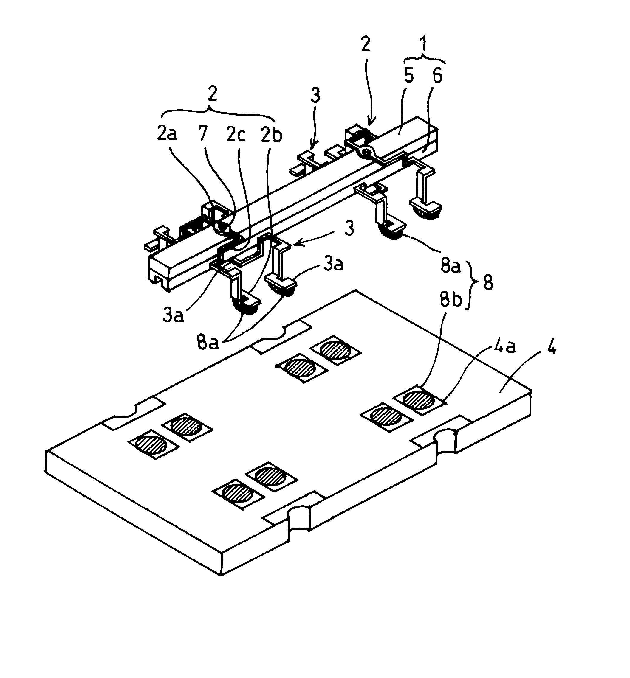
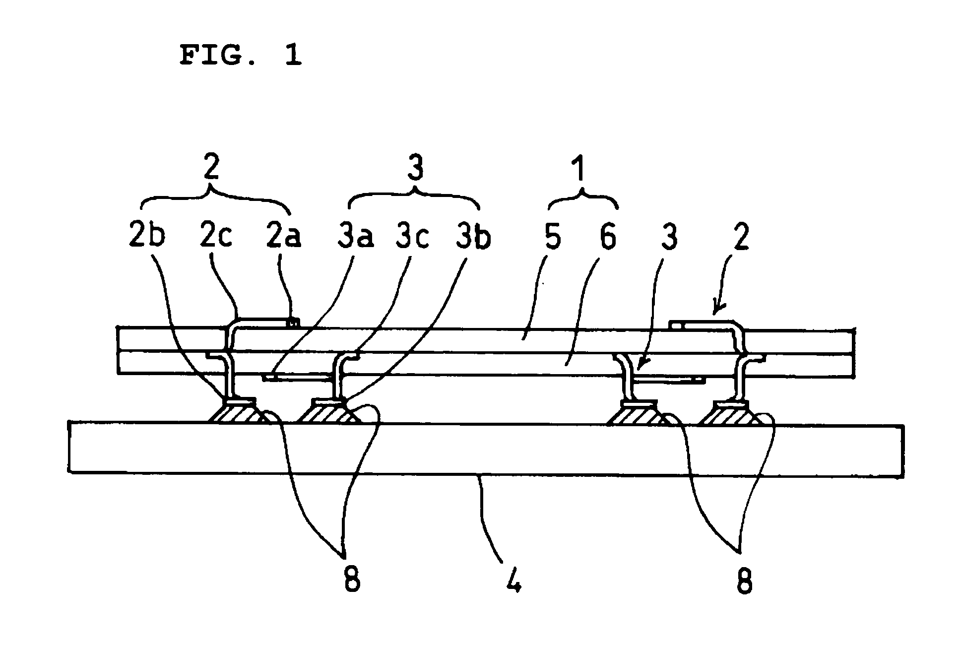
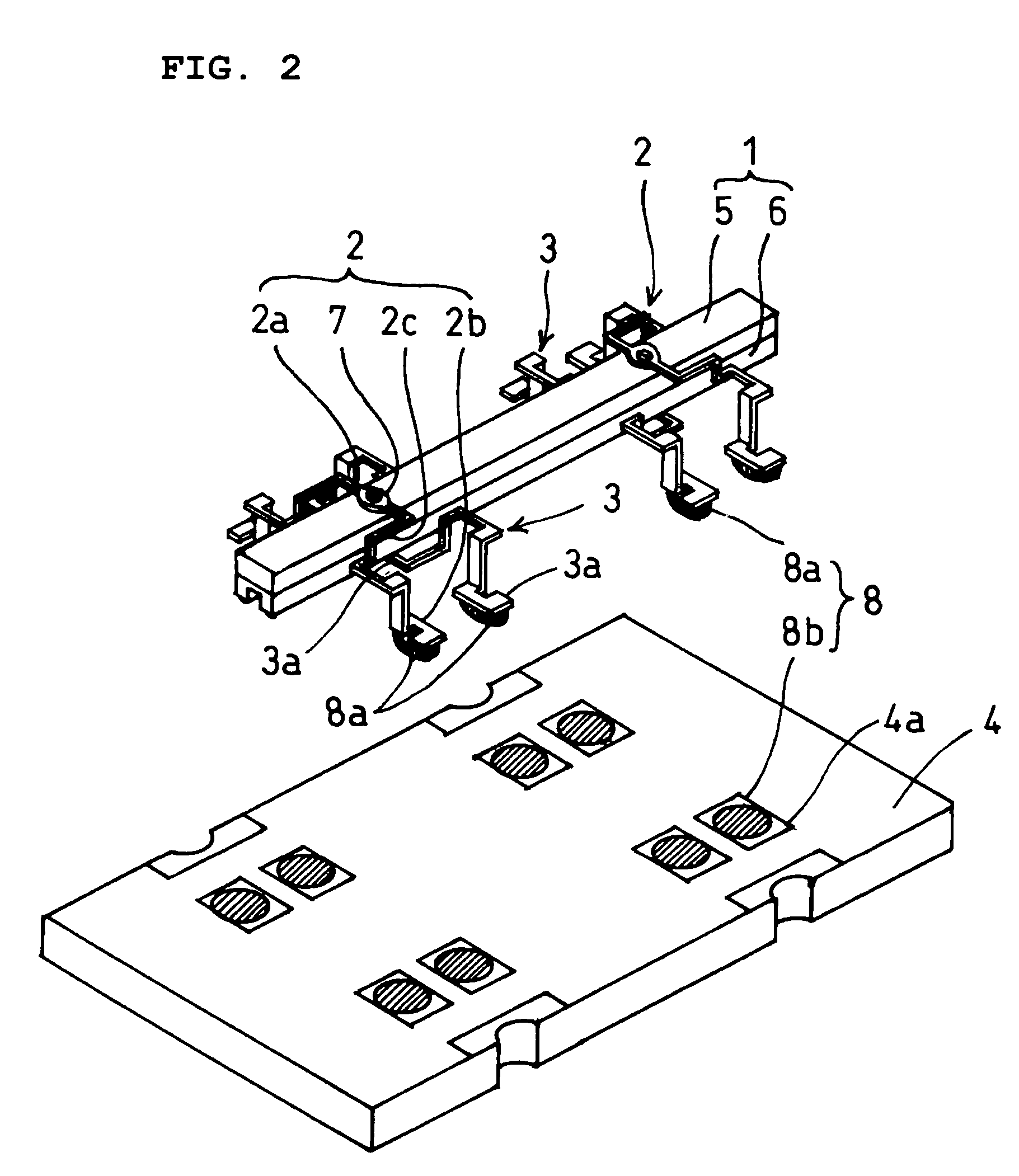
[0022]FIG. 1 is a side view showing the assembled state of a vibrator support structure according to a preferred embodiment of the present invention, FIG. 2 is a perspective view showing the disassembled state of the vibrator support structure according to the present preferred embodiment, and FIG. 3 is an expanded perspective view showing support pins according to the present preferred embodiment. FIGS. 4 and 5 show temperature characteristics of drift of vibrating gyroscopes. The temperature characteristics of drift means the change in output at rest while no angular velocity is applied, that is, the change in output versus temperature at rest. Moreover, in FIGS. 4 and 5, the vertical axis represents output (V) at rest and the horizontal axis represents temperature (° C.).

[0023]The vibrator support structure according to the present preferred embodiment is adopted in vibrating gyroscopes, etc., and, as shown in FIGS. 1 and 2, includes a vibrator 1 preferably in the form of a subst...


PUM


Abstract

In a vibrator support structure, a vibrator is supported on a substrate through support pins, substrate connection portions of the support pins and pin connection portions of the substrate are joined through conductive adhesive which is made of a resin including conductive filler and has a pencil hardness of about 4H or less, and the conductive adhesive has a thickness which can buffer vibrations and impacts propagated through the support pins.

Description

BACKGROUND OF THE INVENTION [0001]1. Field of the Invention[0002]The present invention relates to a vibrator support structure and to a method of manufacturing the support structure.[0003]2. Description of the Related Art[0004]Up to now, in vibrating gyroscopes, a vibrator support structure provided with a vibrator having a bending vibration mode, support pins for supporting the vibrator, and a substrate on which the vibrator is mounted through the support pins has been adopted. That is, in the vibrator, a pair of piezoelectric substrates oppositely polarized in the thickness direction are joined so as to face each other, and one piezoelectric substrate, on which first and second detector electrodes are formed so as to be separated from each other, and the other piezoelectric substrate, on the entire surface of which a drive electrode is formed, are joined so as to sandwich an intermediate electrode.[0005]Then, the support pins are attached to the first and second detector electrode...

Claims


Application Information

Patent Timeline
Patent Type & Authority Patents(United States)
IPC IPC(8): H01L41/053G01C19/56G01C19/5663H01L41/08H01L41/09H01L41/22H01L41/313H05K3/32H05K3/34
CPCG01C19/5663H01L41/053H05K3/321H05K3/3426H05K2201/2045H05K2201/10628H05K2201/10757H05K2201/10848H05K2201/10083Y02P70/50H10N30/88
Inventor KOIKE, MASATOFUJIMOTO, KATSUMI
Owner MURATA MFG CO LTD
Learn More