Injection molded trim resistor assembly

a technology of resistors and components, applied in the direction of resistor details, resistor housings/enclosements/embeddings, adjustable resistors, etc., can solve the problems of increasing the overall size of trim resistor elements, complicating wiring harness insertion, and increasing assembly costs, so as to reduce damage to electrical connections, strengthen and seal joints, and facilitate incorporation

Inactive Publication Date: 2007-01-09
DELPHI TECH INC
View PDF15 Cites 15 Cited by
  • Summary
  • Abstract
  • Description
  • Claims
  • Application Information

AI Technical Summary

Benefits of technology

[0005]In accordance with a preferred embodiment of this invention, a trim resistor assembly comprises a trimmable resistor element embedded within a polymeric housing. The trimmable resistor element includes a nonconductive substrate. A resistive film is disposed on the substrate and includes a trimmable end portion. Also disposed on the substrate are first contact pad and a second contact pad in spaced relationship and in electrical communication with the resistive film. A first lead wire, which includes a metal wire encased within a polymeric sheath, has an end section that is stripped of the sheath and in contact with the first contact pad. Similarly, a second lead wire is provided having an end section formed of the metal wire stripped of th

Problems solved by technology

The two-piece housing requires two molding operations, with associated tooling, and a bonding operation that significantly contribute to the cost of the assembly.
Further, the lateral dimensions of the housing need to be sized to allow a suitable bond to be formed between the polymeric body and top without damage to the trim re

Method used


Image

  • Injection molded trim resistor assembly
  • Injection molded trim resistor assembly
  • Injection molded trim resistor assembly

Examples


Embodiment Construction

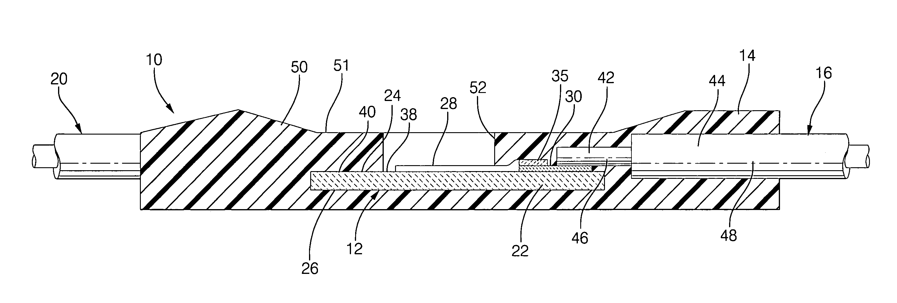
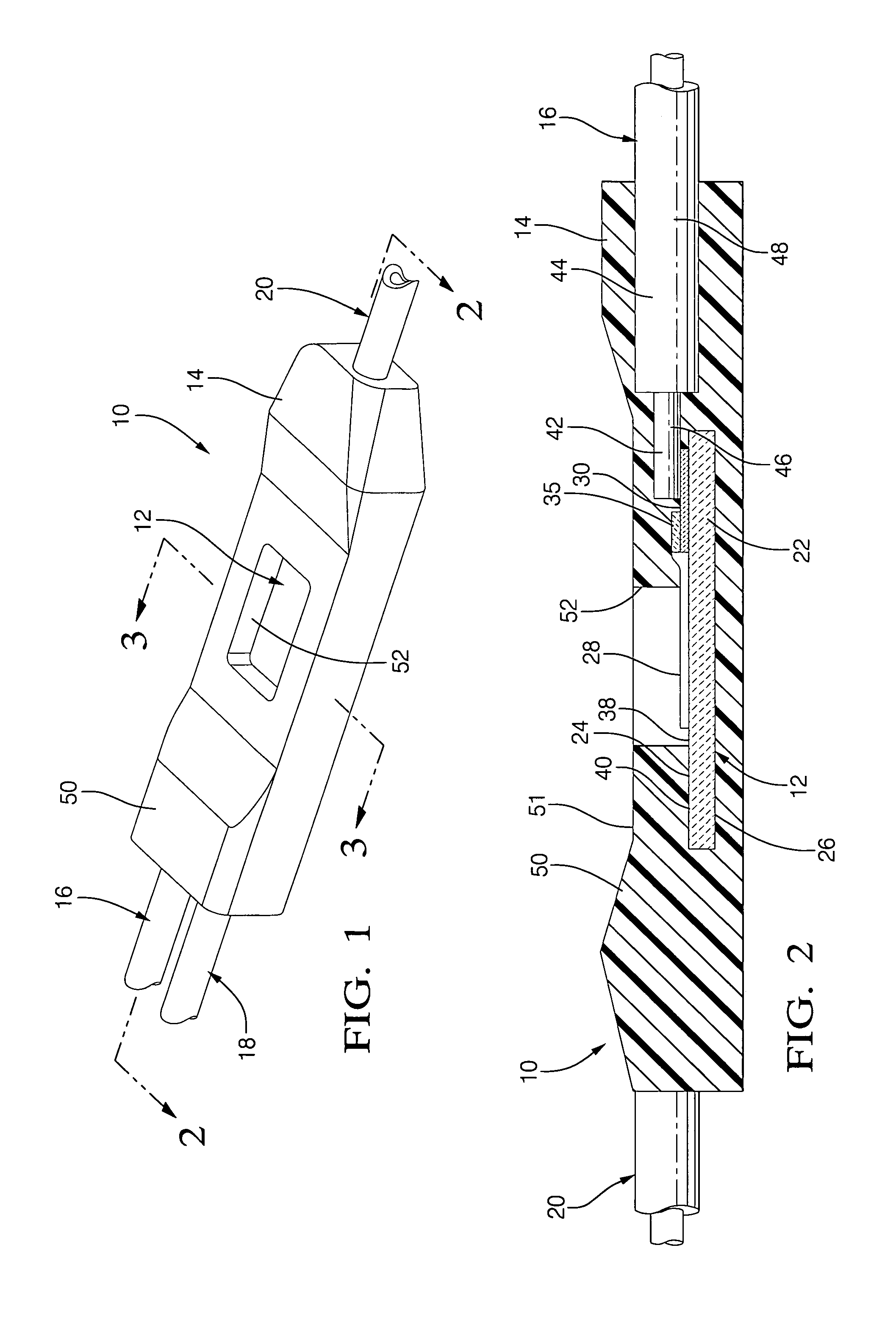
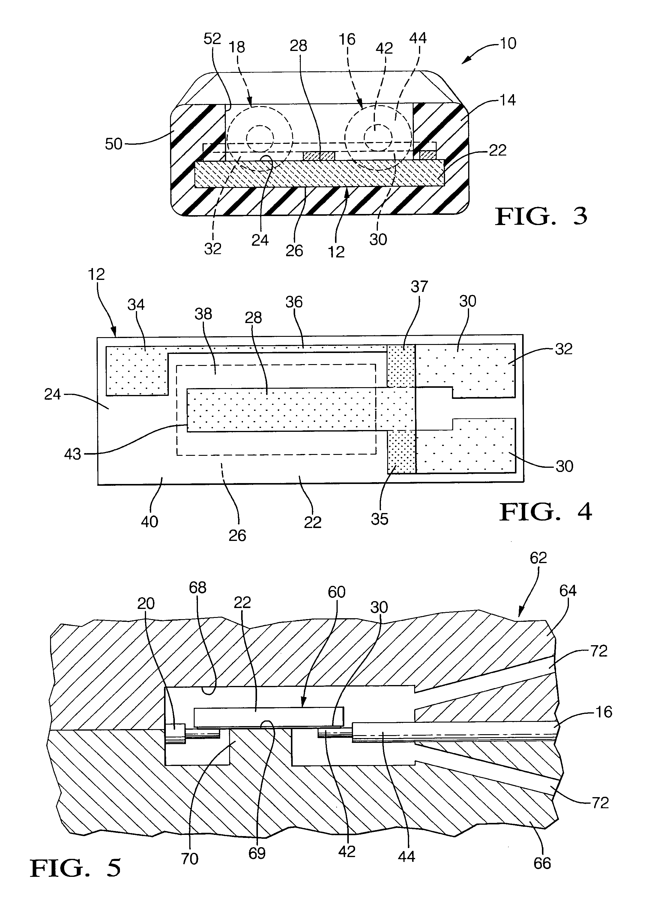
[0013]In accordance with a preferred embodiment of this invention, referring to FIGS. 1 through 4, a trim resistor assembly comprises a trimmable resistor element 12 encased within a polymeric housing 14 and connected to insulated electrical wires 16, 18 and 20.

[0014]Trimmable resistor element 12 comprises a substrate 22 having an obverse face 24 and a reverse face 26. Substrate 22 is formed of a nonconductive material that is preferably able to withstand the resistance trimming operations. A preferred material is alumina, although other ceramic or polymeric materials may be suitable. Referring particularly to FIG. 4, a resistive film 28 is disposed onto face 24 and is formed of an electrical resistive material. A preferred composition comprises ruthenium oxide particles and is readily applied as an ink comprising a volatile solvent. Also disposed on surface 24 are contact pads 30, 32 and 34 in electrical communication with film 28. Pads 30, 32 and 34 are formed of film of an electr...


PUM


Abstract

A trim resistor assembly includes a trimmable resistor element embedded within a polymeric housing. The trimmable resistor element includes trimmable resistive film disposed on a nonconductive substrate. Lead wires are connected to contact pads on the substrate. The resistor element and wires are pre-assembled and placed within a mold defining a cavity. The mold includes a pedestal that covers a central region of the substrate that includes the trimmable resistive film. A polymeric material is injected into the cavity to form an integrally molded body that is the polymeric housing. In addition to the trim resistor element and the bare end sections of the wires, the section of the wires that are adjacent the end sections and include the polymeric sheath are also embedded in the housing to strengthen and seal the joint. The pedestal forms an opening in the housing that exposes the resistive film to provide access for trimming the resistance to a desired value. By embedding the trimmable resistor element and the electrical connections within an integral body, the dimensions of the housing may be minimized, and damage to the electrical connections is reduced.

Description

TECHNICAL FIELD OF INVENTION[0001]This invention relates to a trim resistor assembly, and more particularly, to a trim resistor assembly comprising a trimmable resistive film disposed on a nonconductive substrate and encapsulated within an injection molded polymeric housing having an opening for access to the resistive film for purposes of trimming the resistance.BACKGROUND OF INVENTION[0002]PCT Patent Application Publication WO 02 / 075754 describes a resistor assembly comprising a trim resistor element enclosed within a two-piece housing. The trim resistor element includes an electrically resistive film disposed on a substrate and is received in a recess in a polymeric housing body. A housing top is bonded to the housing body to enclose the trim resistor and has an opening exposing the resistive film. Wires extend through the housing for electrical connection with the film. Following assembly, a laser beam is directed through the opening to remove a portion of the resistive film to ...

Claims


Application Information

Patent Timeline
IPC IPC(8): H01C10/00
CPCH01C1/022H01C17/24H01C7/003
Inventor NELSON, CHARLES SCOTT
Owner DELPHI TECH INC
Why Eureka
Try Eureka