Selectively updating a display in a multi-display system

a multi-display system and display device technology, applied in two-way working systems, digital computers, instruments, etc., can solve the problems of limiting the usability and flexibility of the system, the cost of providing multiple video cards for the computer system, and the limitation of the number of monitors supported (usually two or three), so as to improve the responsiveness of the human interface, improve the graphical data update rate, and improve the quality of the user experience

Inactive Publication Date: 2007-01-09
CLEARCUBE TECHNOLOGY INC
View PDF8 Cites 62 Cited by
  • Summary
  • Abstract
  • Description
  • Claims
  • Application Information

AI Technical Summary

Benefits of technology

[0034]Thus, various embodiments of the systems and methods described herein may provide selective updating of display devices based on activity associated with the display devices, and may thereby improv

Problems solved by technology

Drawbacks to this approach include the cost of providing multiple video cards (or special video cards with multiple outputs) for the computer system, as well as the limitation on the number of monitors supported (usually two or three), due to the limited number of slots and/or buses available on the computer.
This distance constraint severely limits the placement of the multiple video monitors in a system, and thus, limits the usability and flexibility of the system.
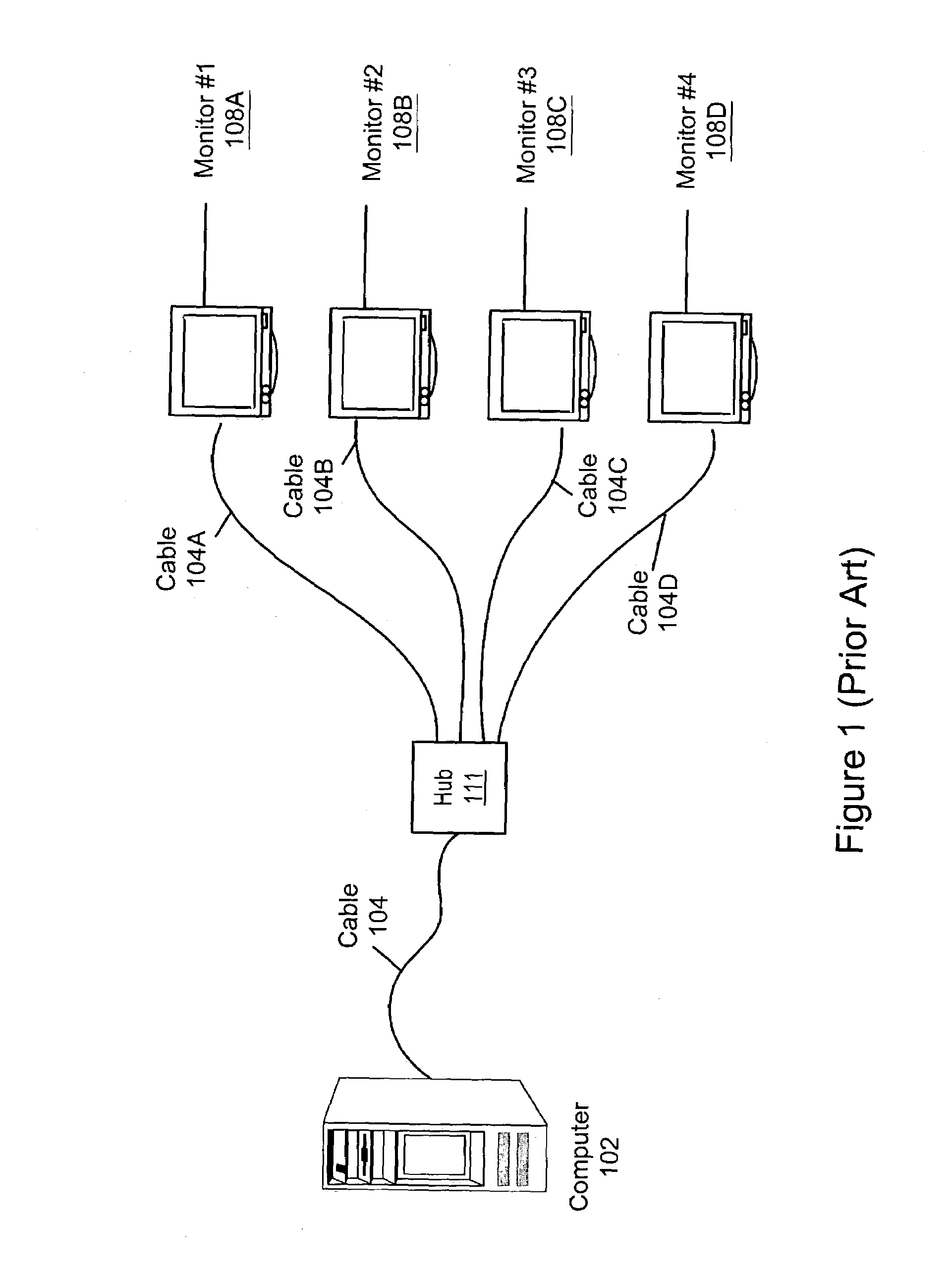
However, current approaches to extended multiple monitor computer systems require individual cables for each monitor.
Thus, if the computer system includes four monitors at the HI location, then four separate cables must be run from the hub to the displays, increasing the expense of the system.
Additionally, in the installation of cabling, the cost of pulling the cable, e.g., through walls, ceilings, etc., may greatly exceed the cost of the cable, and so the use of multiple cables to connect the monitors may involve substantial expense.
The processing involved

Method used


Image

  • Selectively updating a display in a multi-display system
  • Selectively updating a display in a multi-display system
  • Selectively updating a display in a multi-display system

Examples


Embodiment Construction

Incorporation by Reference

[0053]The following patents and patent applications are hereby incorporated by reference as though fully and completely set forth herein:

[0054]U.S. Pat. No. 6,012,101 titled “Computer Network Having Commonly Located Computer Systems” issued on Jan. 4, 2000, whose inventors are Andrew Heller, Barry Thornton, Daniel Barrett, and Charles Ely;

[0055]U.S. Pat. No. 6,119,146 titled “Computer Network Having Multiple Remotely Located Human Interfaces Sharing a Common Computing System” issued on Sep. 12, 2000, whose inventors are Andrew Heller, Barry Thornton, Daniel Barrett, and Charles Ely;

[0056]U.S. Pat. No. 6,038,616 titled “Computer System With Remotely Located Interface Where Signals are Encoded at the Computer System, Transferred Through a 4-wire Cable, and Decoded at the Interface” issued on Mar. 14, 2000, whose inventors are Andrew Heller, Barry Thornton, Daniel Barrett, and Charles Ely;

[0057]U.S. Pat. No. 6,070,214 titled “Serially Linked Bus Bridge For Exp...


PUM


Abstract

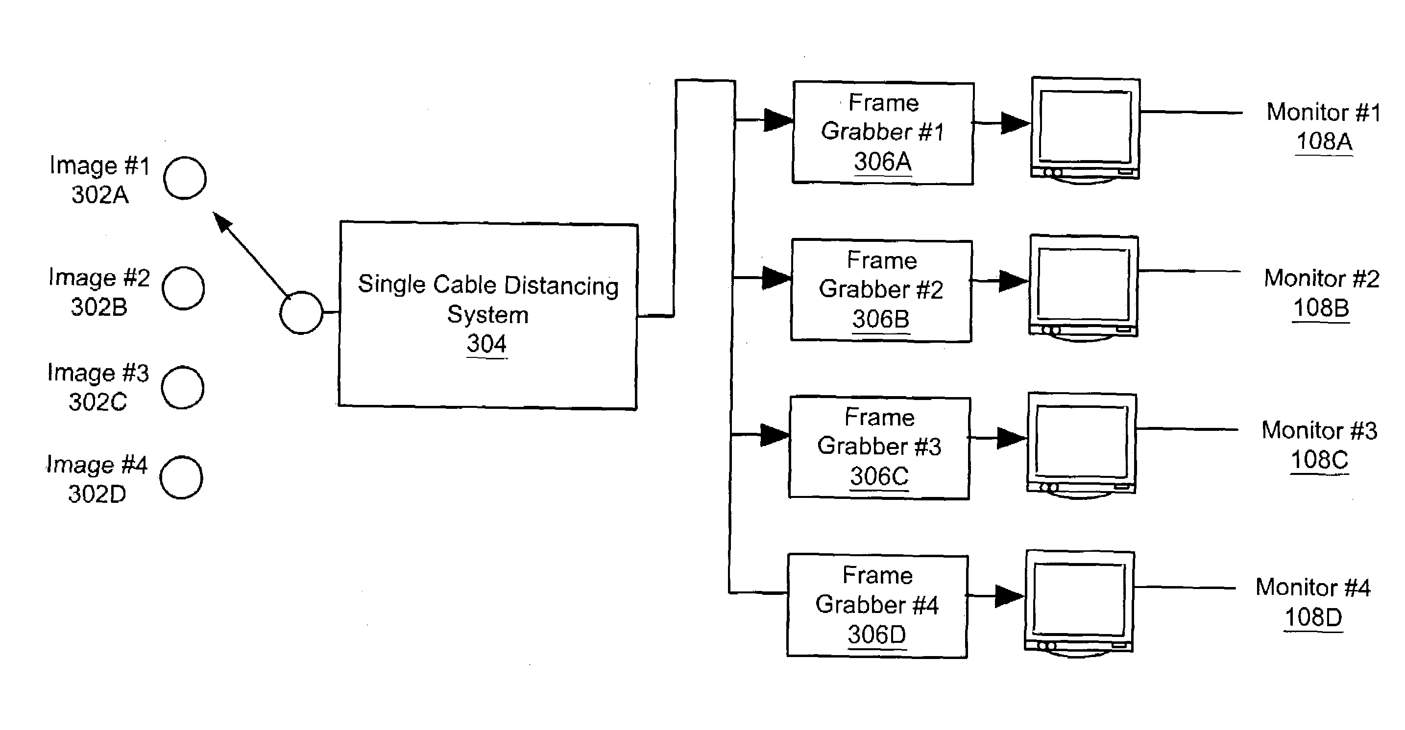
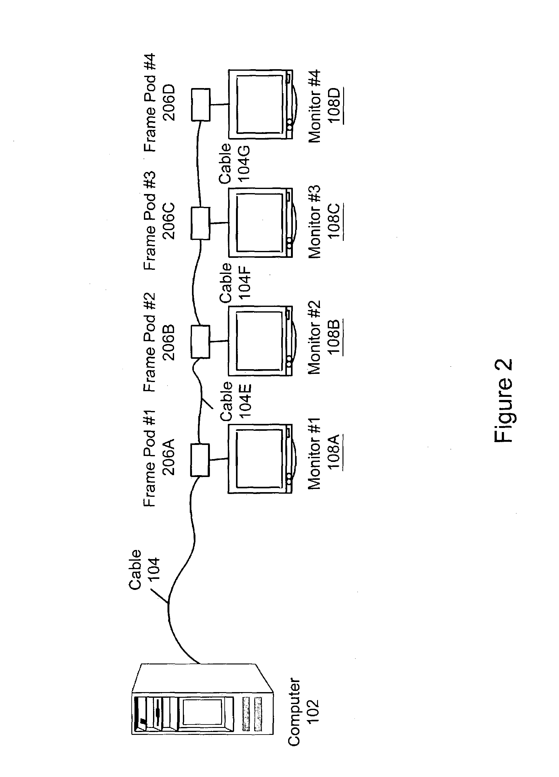
System and method for selectively updating a display in a multiple display device system. Software executing on the computer system analyzes information associated with the display devices, e.g., respective levels of user activity (e.g., peripheral activity), graphics activity (e.g., changes in image data), and/or application activity, associated with each display device, optionally generating priority information associated with the display devices. The display devices are updated in accordance with the analysis using two or more update rates, optionally based on the priority information, e.g., by generating a sequence of video frames based on the analysis, each video frame including a video image and frame identifier designating a display device, and transmitting the sequence over the cable to a plurality of frame grabbers, each frame grabber examining the sequence of video frames, selecting a video frame based on the frame identifier, and forwarding the video frame to the designated display device.

Description

CONTINUATION INFORMATION[0001]This application is a Continuation-In-Part of U.S. patent application Ser. No. 10 / 198,719 entitled “CONNECTING MULTIPLE MONITORS TO A COMPUTER USING A SINGLE CABLE”, filed Jul. 18, 2002, which claims priority to U.S. provisional application Ser. No. 60 / 370,889 entitled “CONNECTING MULTIPLE MONITORS TO A COMPUTER USING A SINGLE CABLE” filed Apr. 8, 2002.BACKGROUND OF THE INVENTION[0002]1. Field of the Invention[0003]The present invention relates generally to operation of multiple display devices with a single computer over a single cable, and more specifically, to selective updating of multiple display devices.[0004]2. Description of the Related Art[0005]The components of a computer system (such as PCs, minicomputers and mainframes) may be divided into two functional units—a computing system and a human interface (or “HI”) to the computing system. For a PC, the computing system may be the CPU, memory, hard drive, power supply and similar components. The ...

Claims


Application Information

Patent Timeline
IPC IPC(8): G09G5/00G06F3/14G06F15/16H04N7/173
CPCG06F3/1431G06F3/1438G09G2370/04G09G2320/103G09G2360/04G09G2300/026G09G5/001
Inventor THORNTON, BARRY W.
Owner CLEARCUBE TECHNOLOGY INC
Why Eureka
Try Eureka