Calibration system for an electronic sign

a technology of electronic signs and calibration systems, applied in the field of electronic sign calibration systems, can solve the problems of easy problems creeping into the process, time-consuming individual calibration of thousands of pixels, and all display technologies used to date slowly lose intensity, so as to reduce the chance of eyestrain, less input, and the effect of reducing the chance of human error

Active Publication Date: 2007-01-09
DAKTRONICS
View PDF5 Cites 70 Cited by
  • Summary
  • Abstract
  • Description
  • Claims
  • Application Information

AI Technical Summary

Benefits of technology

[0018]Another object of the present invention is the invention requires much less input from the operator (i.e., the opportunity for human error is removed from the determination of brighter and dimmer).
[0019]Yet another object of the present invention is the invention decreases the opportunity for eyestrain. The operator must only view the display for a short time during the imaging

Problems solved by technology

However, individually calibrating thousands of pixels is time consuming and it is easy for problems to creep into the process.
Also, all of the display technologies used to date slowly lose intensity over time in a process called degradation.
These issues required display m

Method used


Image

  • Calibration system for an electronic sign
  • Calibration system for an electronic sign
  • Calibration system for an electronic sign

Examples


Embodiment Construction

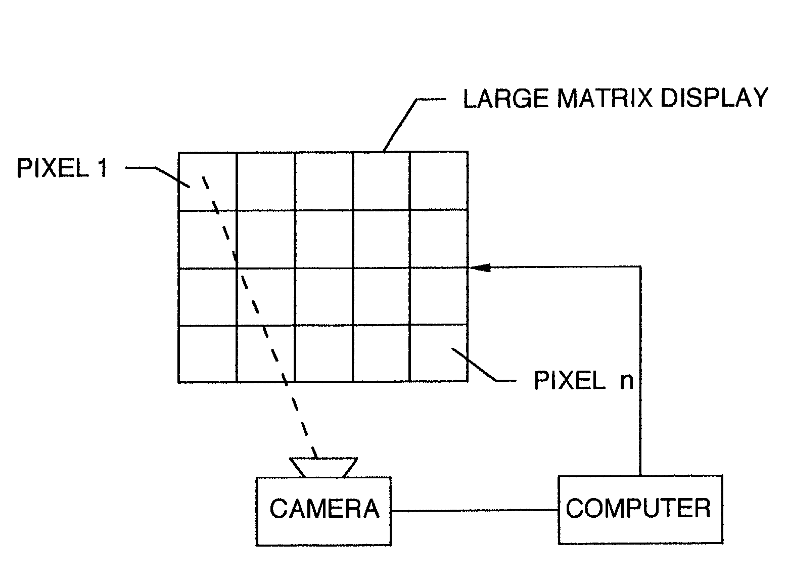
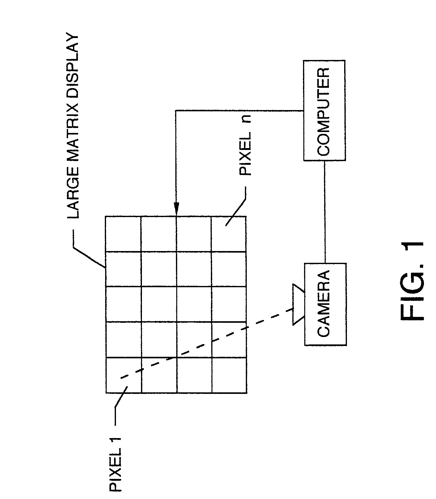
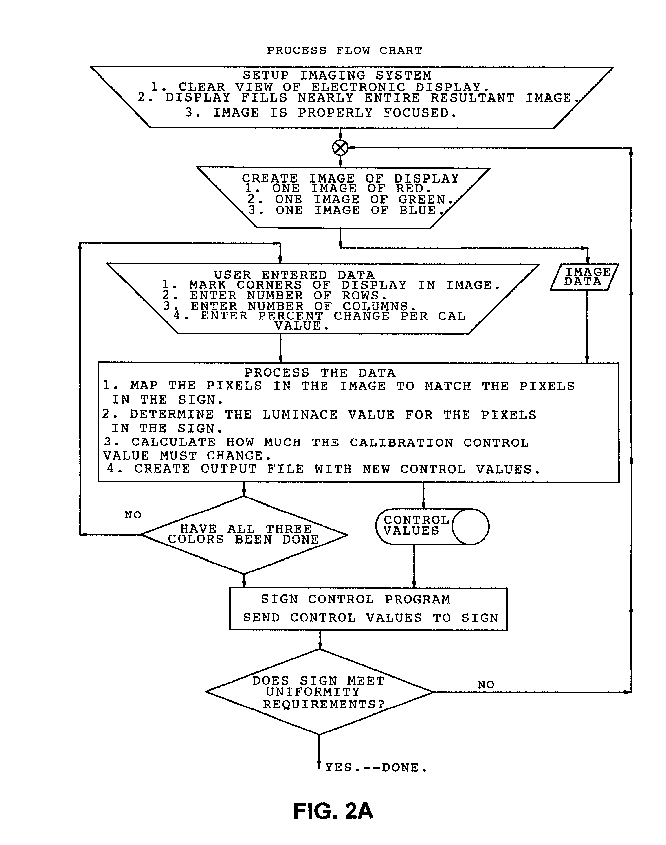
[0024]The imaging system must either produce a color image or use the proper filters to produce a monochrome image. In addition, the imaging system must be of high enough resolution that each pixel in the sign or section of sign is represented by multiple pixels in the imaging system. Finally, the imaging system must have lenses which allow the sign section of interest to nearly fill the available image area of the imaging system. The imaging system is then used to obtain three digital images of the sign. These images are of the entire sign displaying each of the three colors, red, green and blue. These images are then transported to the personal computer.

[0025]The personal computer contains software which interprets the image data from the imaging system and through the use of user supplied parameters uses a formula to convert the image data into control data which corresponds exactly to each display element in the display. This control data will be sent to the electronic sign and ...


PUM


Abstract

Electronically programmed signs consist of any array of picture elements (pixels) that can be controlled independently to create an image. Varying the intensity of each pixel and adding multiple colors per pixel will enhance the image quality. It is currently common to have displays that use one, two or three separate colors in a pixel (monochrome, red-green, and red, green and blue) with intensity levels of two, four, eight up to 256 and beyond. Multiple colored pixels can combine colors at various intensity levels to expand the displayable color palette. The number of colors it is possible to display is calculated by the following formula:
totalnumberofdisplayablecolors=(numberofprimarycolors)(numberofintensitylevelspercolors)
While raising the number of intensity levels and colors improves image quality, it also raises the viewer's sensitivity to inconsistencies in both parameters.

Description

CROSS REFERENCES TO CO-PENDING APPLICATIONS[0001]None.BACKGROUND OF THE INVENTION[0002]1. Field of the Invention[0003]The present invention is in the field of electronically controlled display calibration systems. If the display has the ability to provide intensity offsets for individual pixels, the system can measure and adjust multiple pixels simultaneously in a closed loop system.[0004]2. Description of the Prior Art[0005]Early display systems relied on calibration of individual pixels at the manufacturing level. However, individually calibrating thousands of pixels is time consuming and it is easy for problems to creep into the process. Also, all of the display technologies used to date slowly lose intensity over time in a process called degradation. This caused pixels that were added into the sign due to normal maintenance to appear brighter than the others.[0006]These issues required display manufacturer's to design in the ability to adjust pixel intensity in the field once th...

Claims


Application Information

Patent Timeline
IPC IPC(8): G09G5/00
CPCG09G3/22G09G2320/0233G09G2360/147G09G2320/0693G09G2320/043
Inventor EIDEM, RYAN PAULJOFFER, BRENT ALLANKURTENBACH, REECE ALLENMITTAN, THOMAS RAYMONDSEELEY, ROBERT EDWARD
Owner DAKTRONICS
Why Eureka
Try Eureka