Eureka AIR delivers breakthrough ideas for toughest innovation challenges, trusted by R&D personnel around the world.

Isolation of I2C buses in a multiple power domain environment using switches

a technology of interintegrated circuit buses and switches, applied in the direction of pulse techniques, instruments, liquid/fluent solid measurements, etc., can solve the problems of i2c pins being forward, other devices not being able to communicate with each other, devices may lose power,

Inactive Publication Date: 2007-01-09
HEWLETT-PACKARD ENTERPRISE DEV LP
View PDF11 Cites 18 Cited by
  • Summary
  • Abstract
  • Description
  • Claims
  • Application Information

AI Technical Summary

Benefits of technology

[0010]The first controller is further coupled to a third bus and the second controller is further coupled to a fourth bus. A second switch is coupled between the third and the fourth buses. The second switch is operable to de-couple the third and the fourth buses when the voltage output from the first voltage circuit falls below a predetermined t

Problems solved by technology

A problem that may occur is that one of the devices may lose power, thus causing the electrostatic discharge (ESD) diode on its I2C pin to become forward biased to ground.
When the shared I2C bus is grounded, the other devices cannot communicate with each other even though they remain operational.

Method used


Image

  • Isolation of I2C buses in a multiple power domain environment using switches
  • Isolation of I2C buses in a multiple power domain environment using switches
  • Isolation of I2C buses in a multiple power domain environment using switches

Examples


Embodiment Construction

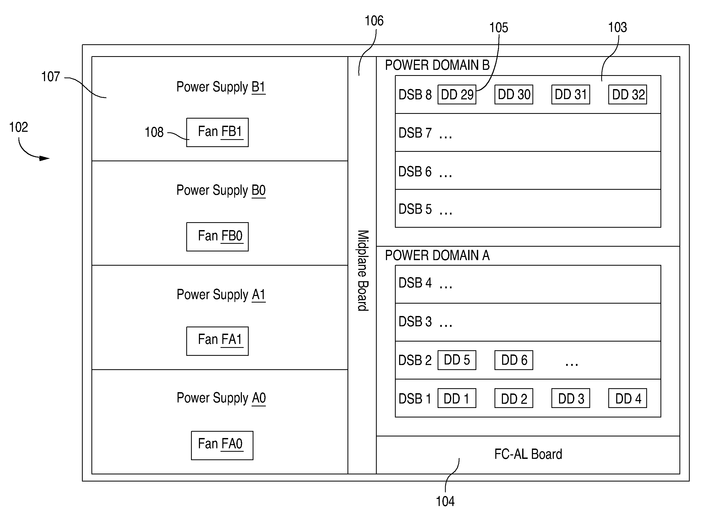
[0022]FIG. 1 is a block diagram illustrating the layout of a disk enclosure 102, according to one embodiment of the present invention. As depicted, enclosure 102 includes eight disk sled boards 103 (only one of which is provided with a reference numeral for clarity). These disk sled boards 103 are separately labeled as DSB1 to DSB8. Each disk sled board 103 includes four disk drives 105 (only one of which is provided with a reference numeral for clarity). These disk drives are separately labeled as DD1–DD32. DD1 to DD4 are on DSB1, DD5 to DD8 are on DSB2, . . . , and DD29 to DD32 are on DSB8. Each disk sled board includes other devices including backplane controllers, port bypass circuits, temperature sensors, and memory devices (shown and described later in reference to FIG. 4). It should be understood, of course, that the number of disk sled boards 103 and disk drives 105 can be varied.

[0023]A number of power supplies 107 (separately labeled as power supply A0, power supply A1, po...


PUM


Abstract

A disk enclosure includes a first enclosure controller powered by a first voltage circuit and coupled to a first I2C bus, a second enclosure controller powered by a second voltage circuit and coupled to a second I2C bus, and a switch coupled between the first and the second I2C buses. The first switch de-couples the first and the second I2C buses when the voltage output of the second voltage circuit falls below a predetermined threshold.

Description

CROSS-REFERENCE TO RELATED APPLICATIONS[0001]This application is related to application Ser. No. 09 / 754,903, filed Jan. 4, 2001, entitled “A DISK ENCLOSURE WITH MULTIPLEXERS FOR CONNECTING I2C BUSES IN MULTIPLE POWER DOMAINS,” and application Ser. No. 09 / 755,285, filed Jan. 4, 2001, entitled “DISK ENCLOSURE WITH MULTIPLE POWER DOMAINS,” which are commonly owned and incorporated by reference herein in their entirety.BACKGROUND[0002]1. Field of the Invention[0003]The present invention relates to storage area networks (SANs) and more specifically to the isolation of inter-integrated circuit buses (I2C buses) in a multiple power domain environment.[0004]2. Description of Related Art[0005]In a SAN environment, storage devices such as digital linear tapes (DLTs) and redundant array of independent disks (RAID arrays) are connected to many kinds of servers via a high-speed interconnection such as Fibre Channel. Standard for Fibre Channel was developed by the American National Standards Inst...

Claims


Application Information

Patent Timeline
IPC IPC(8): G06F13/36H03K17/16
CPCG06F1/30G06F1/189
Inventor PRICE, WILLIAM JOSHUA
Owner HEWLETT-PACKARD ENTERPRISE DEV LP
Why Eureka
Eureka Blog
Learn More