Method of error control coding and decoding of messages in a packet-based data transmission system

a packet-based data and error control technology, applied in the field of packet-based data transmission systems, can solve problems such as the ability of devices to decode data, and achieve the effect of reducing the risk of error propagation and error control coding

Inactive Publication Date: 2007-01-09
INFINEON TECH NORDIC
View PDF9 Cites 18 Cited by
  • Summary
  • Abstract
  • Description
  • Claims
  • Application Information

AI Technical Summary

Benefits of technology

[0020]There is thus a need for a method that enables error control coding with a reduced risk of error propagation and at the same time enables legacy devices to be able to decode at least the header of the frame.

Problems solved by technology

It is, however, not important that legacy devices are able to decode the data portion of the frame, since the proposed solution will only be used between two devices that are aware of the method and have negotiated its use by some higher-level protocol.

Method used


Image

  • Method of error control coding and decoding of messages in a packet-based data transmission system
  • Method of error control coding and decoding of messages in a packet-based data transmission system
  • Method of error control coding and decoding of messages in a packet-based data transmission system

Examples


first embodiment

[0039]A flow chart of the method according to the invention is shown in FIG. 6. The effect of the different stages of the method at a transmitting device on the frame are shown in FIG. 7 (with an 802.11e-like FEC structure being shown as an example, but almost any FEC algorithm can be applied).

At the Transmitting Device:

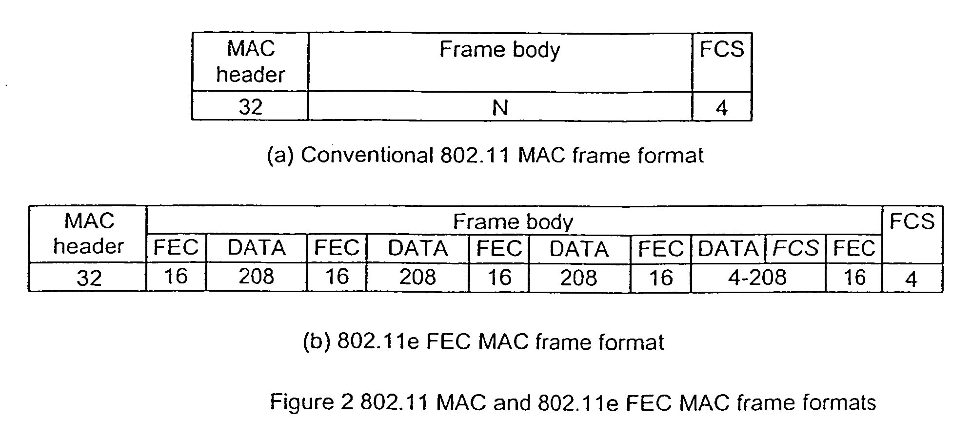
[0040]The PHY layer of a transmitting device receives and formats a conventional 802.11 frame from the MAC layer, including a header (which includes frame length information), a data portion and FCS (or FEC FCS). For the case of 802.11a (or other PHY standards based on 802.11a), the header must also have the 16-bit-Service field (all zeros) prepended to it to allow the descrambler initialization value to be protected by the error control code. It is possible, and may be desirable, to also protect other fields added by the PHY layer.

[0041]Beginning from after the header of the frame, the frame is expanded by means of making spaces or inserting gaps into the frame to a...

second embodiment

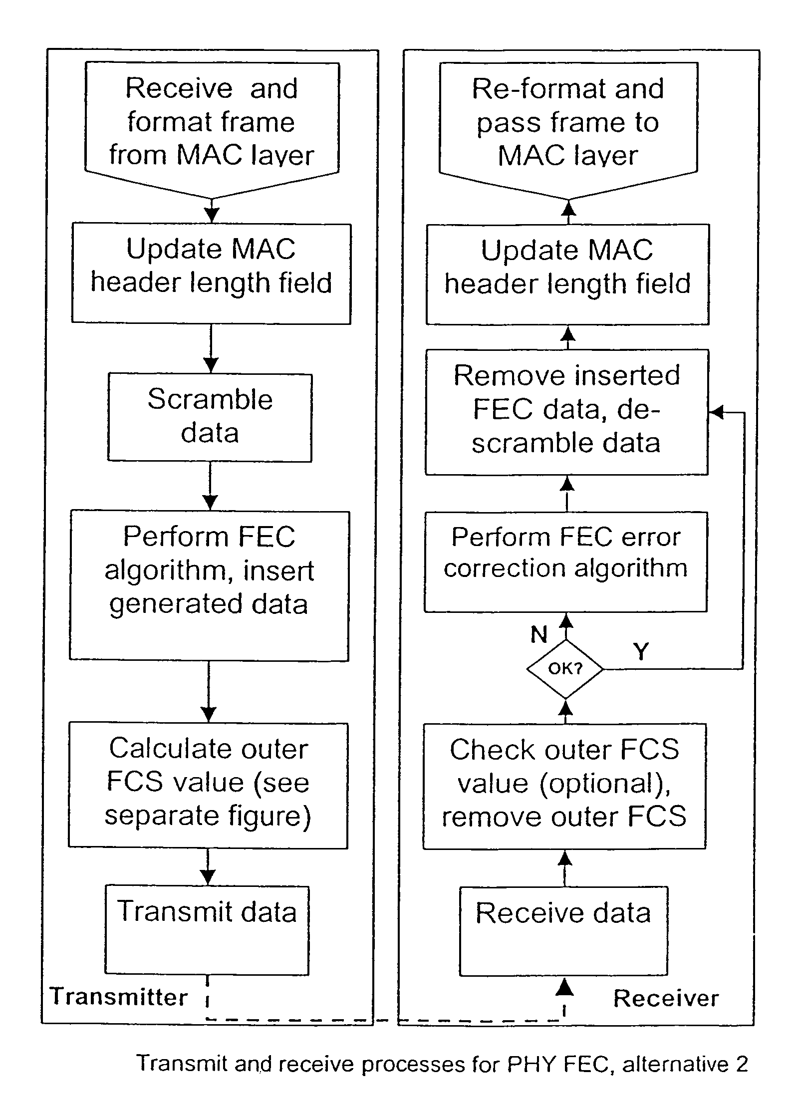
[0050]A flow chart of the second embodiment, between a transmitting device and a receiving device, of the method according to the invention is shown in FIG. 10.

At the Transmitting Device.

[0051]Similarly to the first embodiment according to the invention, the PHY layer of the transmitting device receives a conventional 802.11 frame from the MAC layer, including header, data and FCS (the FEC FCS). For the case of 802.11a (or other PHY standards based on 802.11a), the header must also have the 16-bit Service field (all zeros) prepended to it to allow the descrambler initialization value to be protected by the error control code. It is possible, and may be desirable, to also protect other fields added by the PHY layer.

[0052]In order to enable a future expansion of the frame by insertion of forward error correction data and an outer frame check sequence (OFCS) the length field of the header of the received frame is updated. The frame with the updated header is then scrambled according to...


PUM


Abstract

Initially the message frame comprising a header with length information, a data portion and a check sequence is expanded with gaps inserted to the data portion and the frame check sequence and the frame length information is updated, the frame is then scrambled and forward error correction data is generated and written into the gaps. An outer check sequence is generated and appended as part of the frame, after which the entire frame is transmitted. Error control decoding of the transmitted frame is achieved between reception and descrambling at a receiving device. The outer check sequence is optionally checked and removed, an error correction algorithm is applied to the frame in response to errors, after which the frame is descrambled, the forward error correction data and the inserted gaps are removed and the frame is restored to its original state and the length information is updated to its original value.

Description

CROSS REFERENCE TO RELATED APPLICATION[0001]This application claims the benefit of U.S. provisional application No. 60 / 424,727 filed Nov. 8, 2002, the contents of which are hereby incorporated by reference in their entirety.TECHNICAL FIELD OF THE INVENTION[0002]The invention relates to packet-based data transmission systems in general, and more specifically to a method for error control coding and decoding of messages in packet-based wireless local area networks, where enhanced error control is desired while maintaining backwards compatibility with legacy devices.BACKGROUND OF THE INVENTIONProtocol Stacks and the 802.11 Wireless LAN Standard[0003]Data communication systems are frequently described in terms of a so called protocol stack, which groups the sequences of tasks required to operate the system into logically related groups known as layers. Conceptually, higher layers have a higher level of abstraction; e.g. the user applications are at the highest layer while the circuits r...

Claims


Application Information

Patent Timeline
Patent Type & Authority Patents(United States)
IPC IPC(8): H03M13/00H03M13/03H04L1/00H04L12/28H04L29/06
CPCH03M13/03H04L1/0041H04L1/0061H04L69/22H04L1/0072H04W28/04H04W84/12
Inventor LEWIS, MICHAEL
Owner INFINEON TECH NORDIC
Why Eureka
Try Eureka