Air-fuel ratio control apparatus for internal combustion engine

Inactive Publication Date: 2007-01-16
TOYOTA JIDOSHA KK
View PDF33 Cites 16 Cited by
  • Summary
  • Abstract
  • Description
  • Claims
  • Application Information

AI Technical Summary

Benefits of technology

[0007]An object of the present invention is to provide an air-fuel ratio control apparatus for an internal combustion engine, which apparatus can improve the exhaust gas purifying efficiency of an emission purifying catalyst unit by estimating the

Problems solved by technology

However, the above-described control is adapted to maintain the oxygen storage amount at a level in the vicinity of the target value, and thus, has a problem of being unable to perform air-fuel ratio control for reducing emission of one or more specific components of

Method used


Image

  • Air-fuel ratio control apparatus for internal combustion engine
  • Air-fuel ratio control apparatus for internal combustion engine
  • Air-fuel ratio control apparatus for internal combustion engine

Examples


first embodiment

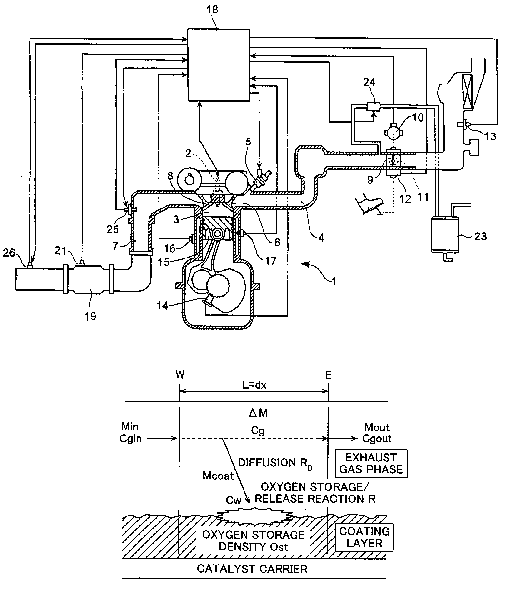
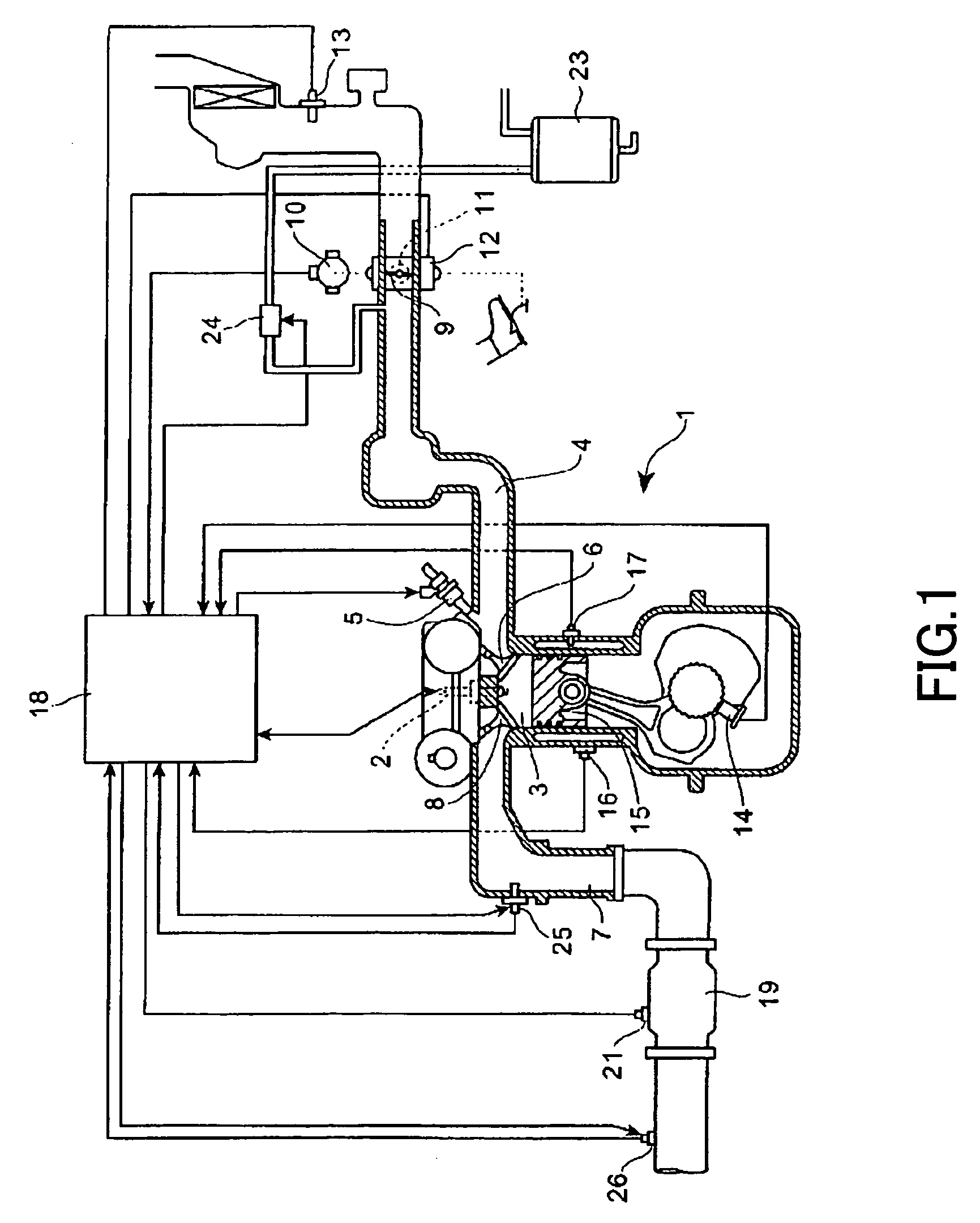
[0207]First, a first embodiment will be described with reference to FIG. 18, which shows a control flowchart thereof. In the present embodiment, the amount of oxygen in exhaust gas (in actuality, the concentration of oxygen discharged from the catalyst unit 19) and the amount of carbon monoxide in the exhaust gas (in actuality, the concentration of carbon monoxide discharged from the catalyst unit 19) are obtained as the above-described estimation values. Further, in air-fuel ratio control, oxygen amount is handled as an excess or deficient amount of oxygen. That is, when oxygen is present in an excessive amount, the oxygen amount assumes a positive value, and when oxygen is deficient, the oxygen amount assumes a negative value. Moreover, in the present embodiment, the entirety of the catalyst unit 19 is considered to be a single region (specific region).

[0208]In the exhaust gas purification reaction at the catalyst unit 19, oxygen is consumed in order to oxidize a to-be-removed com...

second embodiment

[0217]Next, a second embodiment will be described with reference to FIG. 20, which shows a control flowchart thereof. In the present embodiment, rich and lean components of the exhaust gas are used as the above-described estimation values. Further, in the present embodiment, the entirety of the catalyst unit 19 is considered to be a single region (specific region).

[0218]The rich component collectively refers to components whose contents in the exhaust gas increase when the exhaust air-fuel ratio is on the rich side, and is one representative value that shows the state of the exhaust gas flowing out of the catalyst unit 19. Specifically, it is a representative value that serves a collective index representing the amounts of CO and HC contained in the exhaust gas. Meanwhile, the lean component collectively refers to components whose contents in the exhaust gas increase when the exhaust air-fuel ratio is on the lean side, and is one representative value that shows the state of the exha...

third embodiment

[0228]Next, a third embodiment will be described with reference to FIG. 21, which shows a control flowchart thereof. In the present embodiment, emissions (in actuality, concentrations) of oxygen, carbon monoxide, and nitrogen monoxide contained in exhaust gas are used as the above-described estimation values. Further, in the present embodiment, the entirety of the catalyst unit 19 is considered to be a single region (specific region). In the present embodiment, since air-fuel ratio control is performed by use of the above-mentioned three estimation values, in the following description, Cgout in relation to oxygen emission is represented by CgoutO2 (Cgout,O2) , Cgout in relation to carbon monoxide emission is represented by CgoutCO (Cgout,CO), and Cgout in relation to nitrogen monoxide emission is represented by CgoutNO (Cgout,NO).

[0229]As shown in the flowchart of FIG. 21, in the first step, step 140, the CPU estimates CginR (Cgin,CO) and CginL (Cgin,O2, Cgin,NO) of the rich and lea...


PUM


Abstract

An air-fuel ratio control apparatus estimates, on the basis of an exhaust air-fuel ratio of exhaust gas flowing into an exhaust purifying catalyst unit disposed in an exhaust passage of an engine, an emission of at least one specific component contained in exhaust gas flowing out of the exhaust purifying catalyst unit. The air-fuel ratio control apparatus performs the estimation by use of a model, and controls the air-fuel ratio in such a manner that the estimation value reaches a target state. The model is previously determined in consideration of the mass balance of the specific component.

Description

TECHNICAL FIELD[0001]The present invention relates to an air-fuel ratio control apparatus for an internal combustion engine.BACKGROUND ART[0002]Conventionally, in order to purify exhaust gas from an internal combustion engine, an emission purifying catalyst unit (three-way catalyst unit) is disposed in an exhaust passage, and feedback control is performed on the basis of an air-fuel ratio detected by means of an air-fuel ratio sensor provided in the exhaust passage in such a manner that the air-fuel ratio of an air-fuel mixture supplied to an engine attains a stoichiometric air-fuel ratio (theoretical value). Thus, nitrogen oxides (NOx), carbon monoxide (CO), and hydrocarbons (HC) are reduced concurrently. Accurate performance of the above-mentioned feedback control is effective for improving the degree of purification of exhaust gas from an internal combustion engine.[0003]Moreover, in an effort to further improve the exhaust purifying performance of an emission purifying catalyst ...

Claims


Application Information

Patent Timeline
IPC IPC(8): F01N3/00B01D53/94F01N3/08F01N3/28F01N9/00F02D35/00F02D41/00F02D41/02F02D41/14
CPCB01D53/9495F01N3/2828F01N9/005F02D41/025F02D41/1455F02D41/1465F01N3/0828Y02T10/47F01N2330/06F01N2430/06F01N2570/10F01N2570/12F01N2570/14F01N2570/16F02D41/003F02D41/1441F02D41/1456F02D2041/1433F02D2200/0802Y02T10/26Y02T10/12Y02T10/40F01N9/00
Inventor NAGAI, TOSHINARIKATAYAMA, AKIHIROKATO, NAOTOKURODA, YUKIOKUZE, YASUHIROSAWADA, HIROSHIUCHIDA, TAKAHIROBABA, NAOKIKOJIMA, SHINJI
Owner TOYOTA JIDOSHA KK
Why Eureka
Try Eureka