Thread switch upon spin loop detection by threshold count of spin lock reading load instruction

a technology of load instruction and threshold count, which is applied in the direction of computation using denominational number representation, instruments, multi-programming arrangements, etc., can solve the problems of delay in synchronization between threads, and interference with other thread processing, so as to reduce processing delays, increase processing speed, and efficiently assign processing

Inactive Publication Date: 2007-01-16
FUJITSU LTD
View PDF11 Cites 24 Cited by
  • Summary
  • Abstract
  • Description
  • Claims
  • Application Information

AI Technical Summary

Benefits of technology

[0020]The present invention has been developed with a view to eliminating the above-mentioned problems, and it is therefore an object of the present invention to prevent a wait condition stemming from a loop from interfering with the execution of other threads without retouching software.
[0036]According to the present invention, the thread switching is made when an instruction string loop is detected, which can reduce the delays of the processing due to the loop and can efficiently assign the processing in the processor to a plurality of threads to increase the processing speed, and which permits the realization by hardware without retouching software, thus allowing the application to the existing processor system and providing great convenience.

Problems solved by technology

Moreover, in this VMT method, with respect to threads in which cache miss is hard to develop, the switching to a different thread is made when a given period of time elapses.
When a great deal of processor processing time is spared for such meaningless processing, the performance of the processor degrades and the completion of the synchronization between the threads delays.
That is, the wait condition in the spin-loop interferes with the other thread processing.
However, although this conventional thread switching control in a processor is effective to a newly developed program or recompile-possible program, difficulty is encountered in employing it for recompile-impossible program or change-impossible program, such as in the case of the loss of a program source.

Method used


Image

  • Thread switch upon spin loop detection by threshold count of spin lock reading load instruction
  • Thread switch upon spin loop detection by threshold count of spin lock reading load instruction
  • Thread switch upon spin loop detection by threshold count of spin lock reading load instruction

Examples


Embodiment Construction

[0056]An embodiment of the present invention will be described hereinbelow with reference to the drawings.

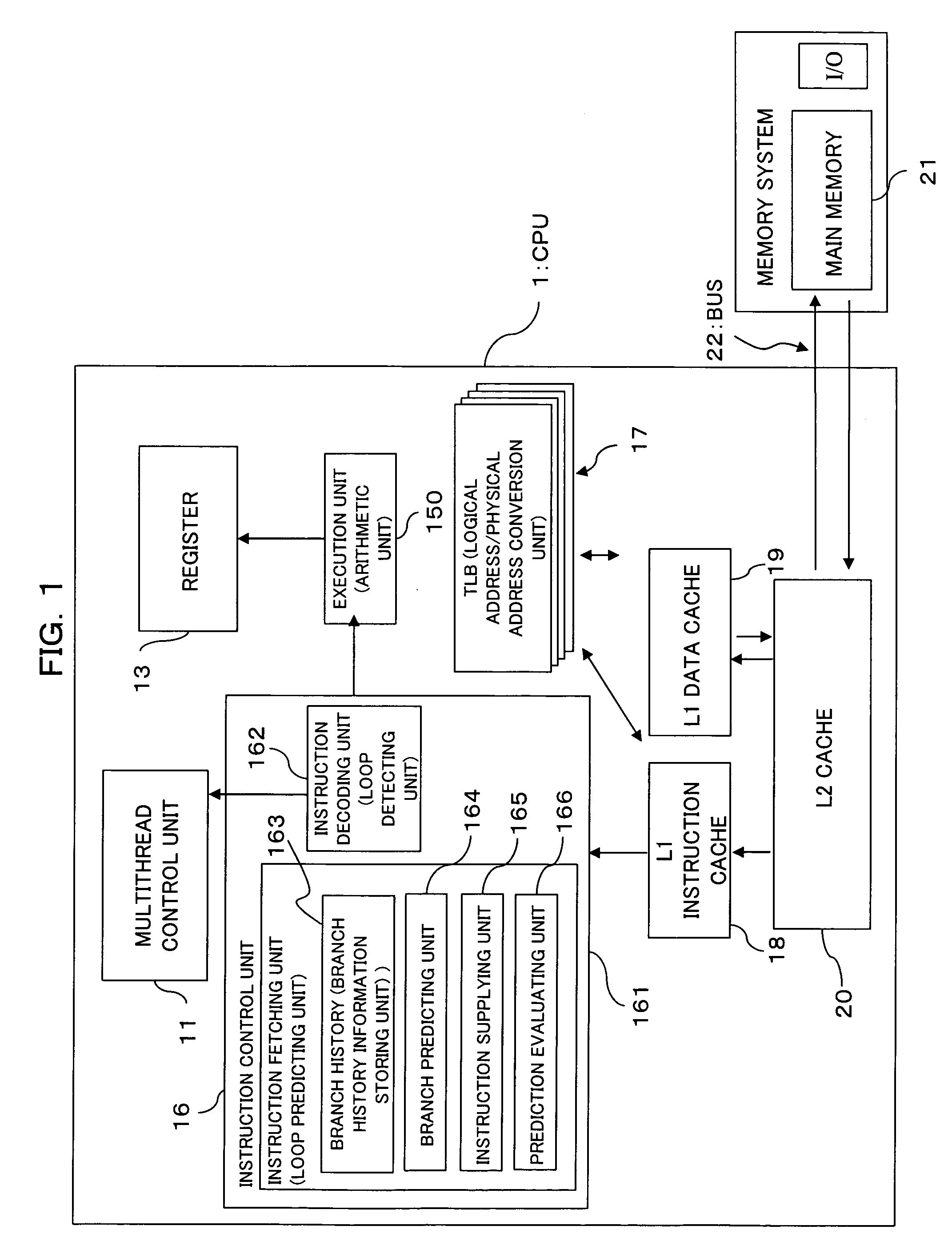
[0057]FIG. 1 is a block diagram showing a configuration of a processor system according to an embodiment of the present invention.

[0058]A CPU (Central Processing Unit) 1 serving as a processor system according to the embodiment of the present invention is constructed as a multithread processor capable of carrying out plurality of threads (programs) in parallel through the use of one or more execution units (arithmetic units) 150.

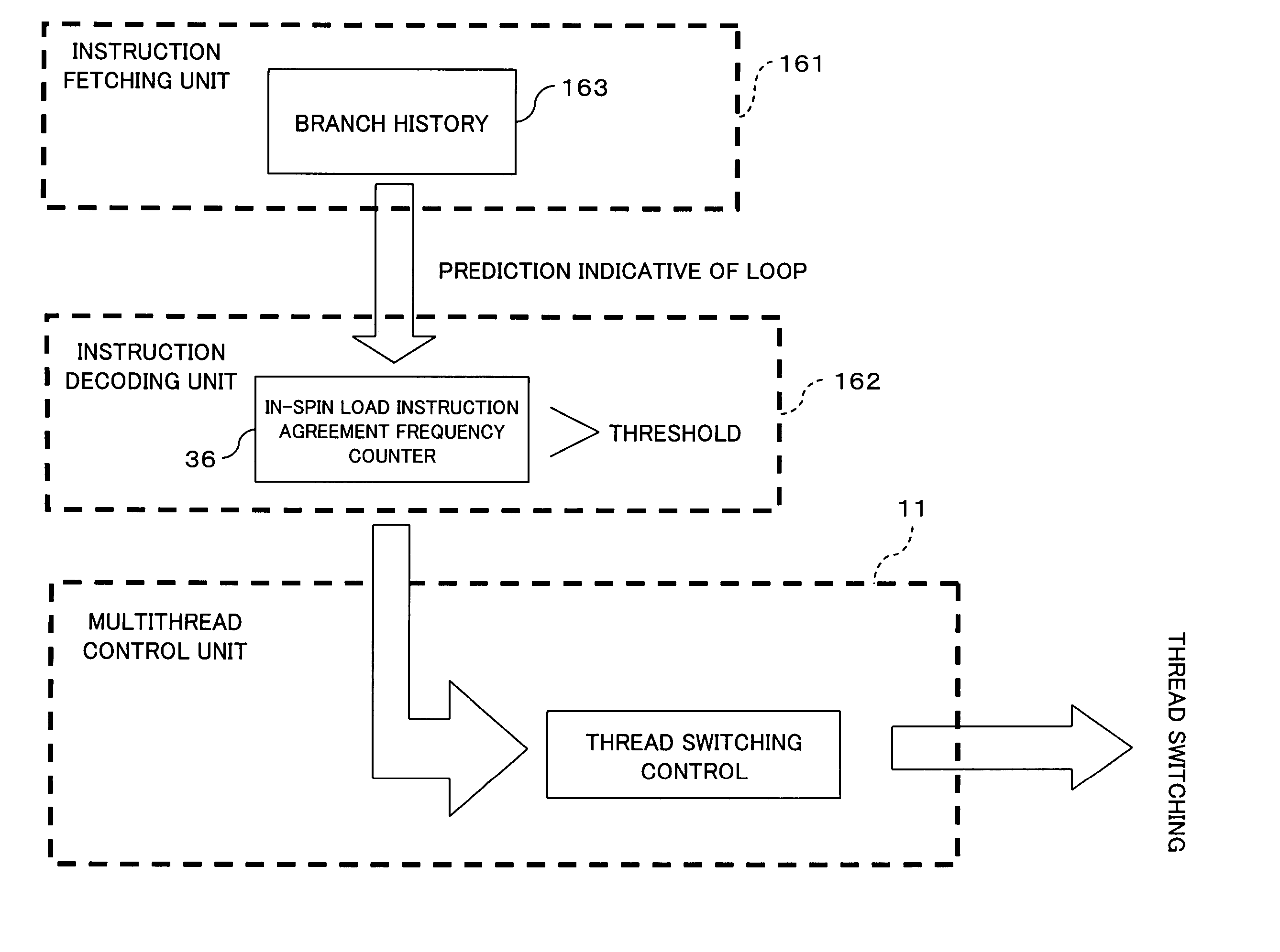
[0059]In addition, this CPU 1 has a so-called spin-loop detectable hardware configuration which monitors data (shared data, monitored data) to be stored in one specified area on a memory and makes a loop to continue waiting until the value of the monitored data reaches an expected value.

[0060]In this case, the spin-loop to be detected by the CPU 1 according to the present invention signifies an instruction string which continuously monitors one portion o...


PUM


Abstract

The present invention relates to a processor system. The processor system is made up of a multithread control unit for selectively making switching among said threads to be executed in an arithmetic unit, a loop predicting unit for predicting a loop of an instruction string on the basis of a processing history of a branch instruction in the thread, and a loop detecting unit for, when the loop predicting unit predicts the loop, detecting the loop on the basis of an instruction. When the loop detecting unit detects the loop, the multithread control unit making the switching from the thread, which is in execution in the arithmetic unit, to a different thread. This prevents a wait condition stemming from the loop from interfering with the execution of other threads without retouching software.

Description

BACKGROUND OF THE INVENTION[0001](1) Field of the Invention[0002]The present invention relates to thread switching control in a processor system.[0003](2) Description of the Related Art[0004]In the recent years, as the representatives of computer architectures, in addition to a CISC (Complex Instruction Set Computer) architecture designed to carry out complex processing in accordance with one instruction, there have been known an RISC (Reduced Instruction Set Computer) architecture made to simplify processing to be implemented relative to one instruction, a VLIW (Very Long Instruction Word) made to collect a plurality of simultaneously processible instructions into one long instruction through software, and other architectures.[0005]In addition, the processing methods in a central processing unit (CPU) of a computer for realizing these architectures are roughly classified into two: in-order execution type and out-of-order execution type.[0006]FIG. 13 is an illustration for explainin...

Claims


Application Information

Patent Timeline
Patent Type & Authority Patents(United States)
IPC IPC(8): G06F9/50
CPCG06F9/325G06F9/3851G06F9/3844
Inventor YOSHIDA, TOSHIO
Owner FUJITSU LTD
Why Eureka
Try Eureka