Method for exploitation of gas hydrates

a technology of gas hydrate and hydrate, which is applied in the direction of survey, wellbore/well accessories, insulation, etc., can solve the problem of hydrate itself dilution in sediment, and achieve the effect of enhancing the production process and preventing methane leakage to the atmospher

Inactive Publication Date: 2007-01-23
SCHLUMBERGER TECH CORP
View PDF9 Cites 41 Cited by
  • Summary
  • Abstract
  • Description
  • Claims
  • Application Information

AI Technical Summary

Benefits of technology

[0008]Downhole production mechanisms, including valves, pipes and sensors, allow controlled flow of the aquifer water into the hydrate zone through the completion. This completion may include a fracture, particularly a horizontal fracture. The production mechanisms may also allow production of the released gas through a completion (possibly including another horizontal hydraulic fracture) placed higher in the hydrate zone through the same or another vertical or horizontal wellbore. For thick hydrate deposits (i.e., several hundred meters), several layers of completions / horizontal fractures may initially be used in order to efficiently release and collect the gas. For thinner hydrate deposits a single completion / horizontal fracture may be created towards the upper part of the hydrate deposit. The production mechanisms installed may further be used to alternate between the flow of water from the warm aquifer and production of released gas to surface. In certain cases, it may be beneficial to produce the water injected into the hydrate zone along with the released gas and replenish the hydrate zone with fresh warm water from the aquifer. The produced water can be either reinjected into an aquifer or disposed off appropriately.
[0009]Any number of sensors may be deployed to track downhole performance via measurements of temperature, pressure and flow rates within the production well or in separate monitoring wells. For instance, temperature may be monitored through side track wells to ensure that the upper portions of the hydrate layer both near and away from the production well do not decompose, in order to prevent methane leakage to the atmosphere. Gas and acoustic detectors may also be used. The input from the sensors can guide the activation of the appropriate downhole valve to control the heating of the sediment by adjusting the water injection. The producing wells are typically tied to a large pipeline that conducts the produced gas towards a compressor station and onward for further processing / distribution. For hydrate formed in sediments, the fractures could enhance significantly the production process. Since constant heating of the hydrate layer may be needed the water injected into the hydrate may have to be produced periodically, and replenished with fresh warm water from the aquifer below.

Problems solved by technology

Often however, the hydrate itself is dilute in the sediment, occupying 2% of the volume on average.
One of the key problems in exploiting these hydrate deposits involves finding appropriate methods to produce and collect the gas.

Method used


Image

  • Method for exploitation of gas hydrates
  • Method for exploitation of gas hydrates
  • Method for exploitation of gas hydrates

Examples


Embodiment Construction

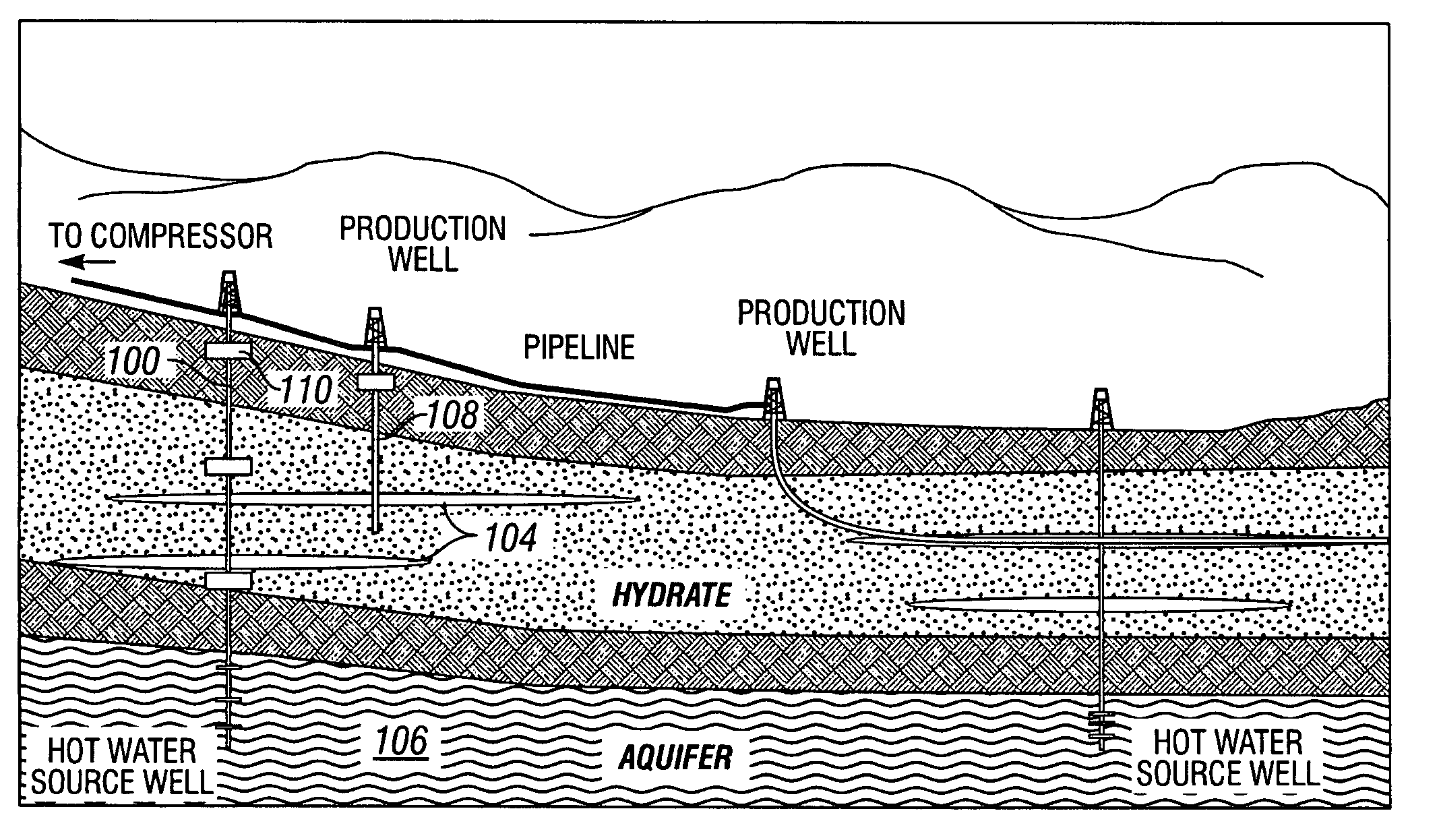
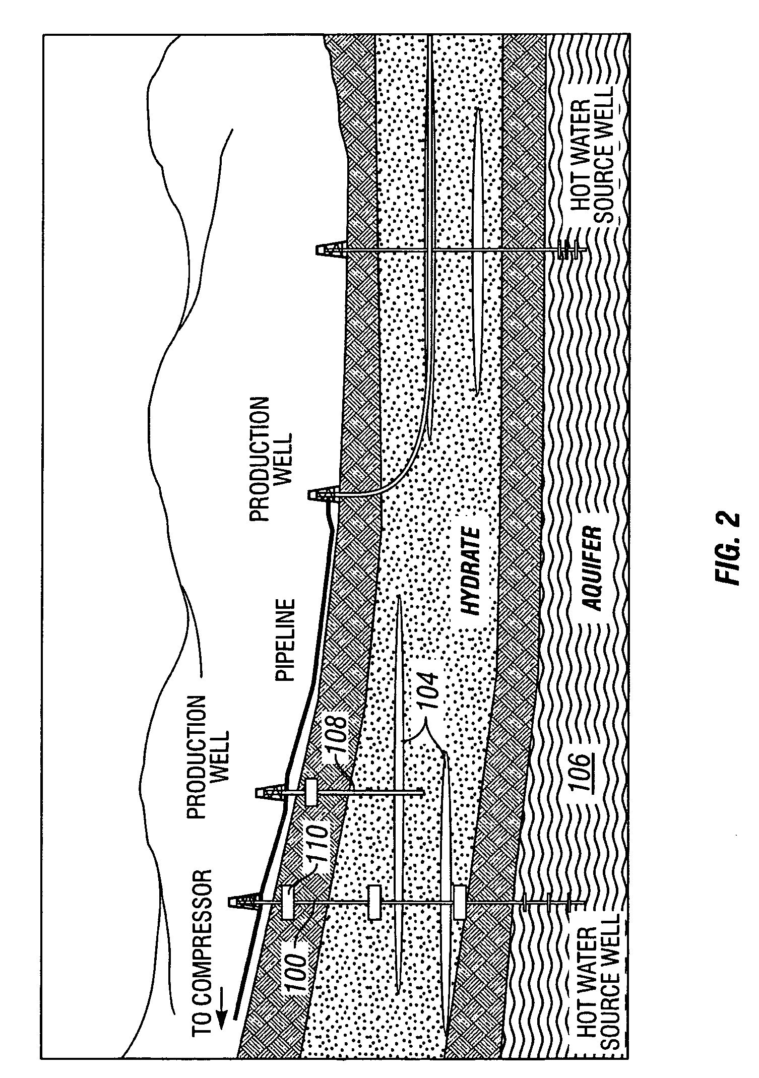
[0015]The present invention is a method for producing gas from gas hydrate formations using relatively warmer water from an aquifer or other water-producing formation or zone below the hydrate formation.

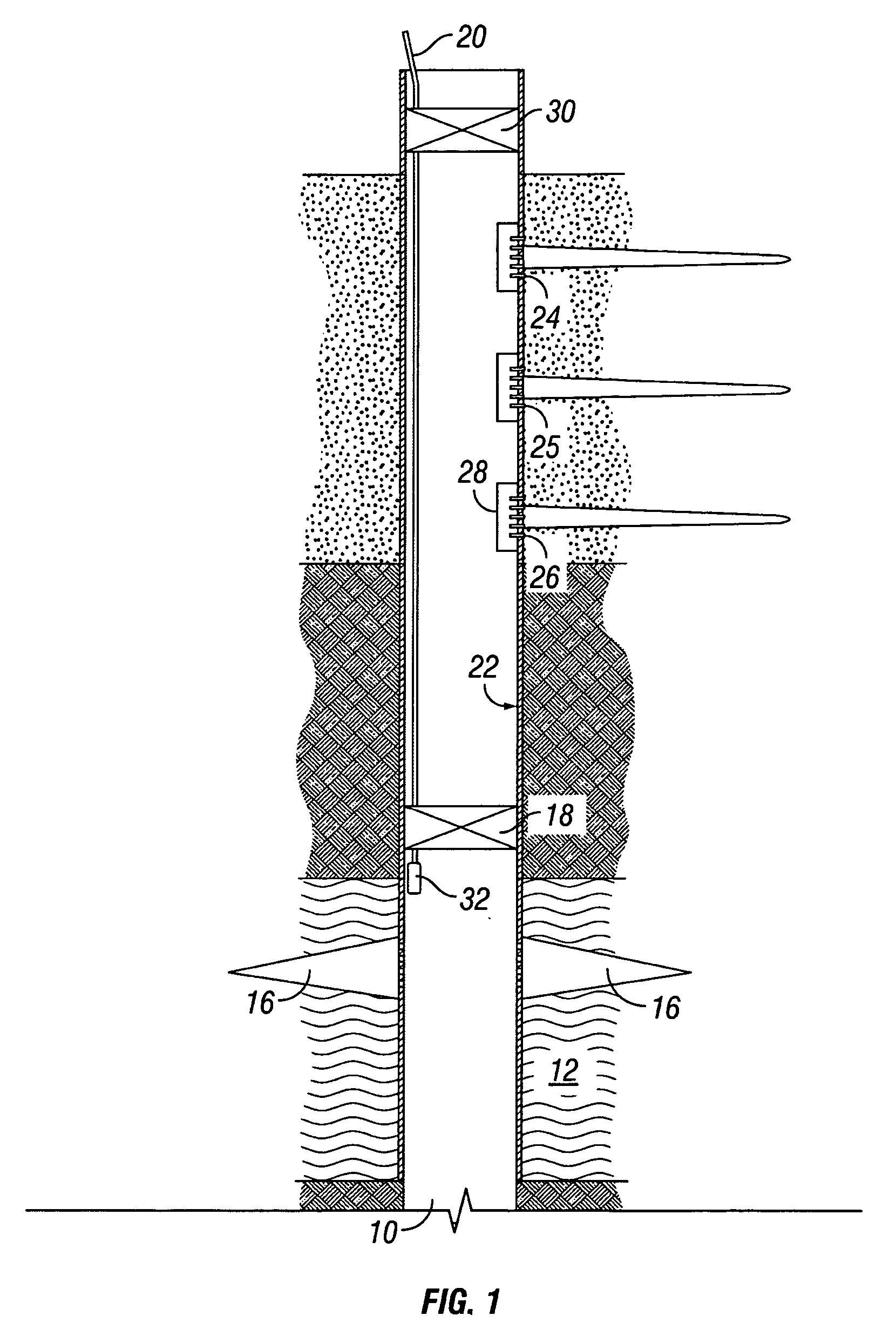
[0016]FIG. 1 shows a first embodiment of the invention, wherein a single cased wellbore 10 is used to produce water from an aquifer 12 or other water-producing formation or zone and to produce gas generated from a gas hydrate formation 14. The wellbore extends through the gas hydrate formation and into the aquifer. Said aquifer is preferably located or positioned substantially below (i.e., deeper) than the hydrate formation. Depending on the specific features of the aquifer, it may be desirable to perform a stimulation operation to increase water output. This may involve hydraulic fracturing, acidizing or the like. Similarly, it may also be desirable to fracture the hydrate deposit prior to treatment with water from the aquifer. Where necessary, the aquifer water may be suitable pres...


PUM


Abstract

A method and apparatus for producing gas from a hydrate formation includes the use of at least one wellbore which penetrates the hydrate formation and further extends into an aquifer below the hydrate formation. The aquifer provides relatively warm water which may be produced up and into the hydrate formation thereby causing the release of gas from the hydrate. Suitable flow control and monitoring equipment may be included to control the flow of water produced from the aquifer and gas produced from the hydrate formation.

Description

BACKGROUND OF THE INVENTION[0001]1. Field of the Invention[0002]The present invention relates generally to a method of producing gas from gas hydrates. More specifically, the invention is a method for contacting a gas hydrate formation with warmer water from an aquifer to release sequestered gas.[0003]2. Description of the Prior Art[0004]A gas hydrate is a crystalline solid that consists of a gas molecule surrounded by water molecules. The structure is similar to ice, except that the crystalline structure is stabilized by the presence of the gas molecule. The two molecules are dissimilar, but mechanically intermingled, without true chemical bonding. Gas hydrates may be formed of a number of gasses having an appropriate molecular size. These include carbon dioxide, hydrogen sulfide and several low-carbon-number hydrocarbons, including methane. Natural gas hydrates are modified ice structures enclosing methane and possibly other hydrocarbons.[0005]Hydrates tend to form in the pore spa...

Claims


Application Information

Patent Timeline
Patent Type & Authority Patents(United States)
IPC IPC(8): E21B43/00E21B36/00
CPCE21B41/0064E21B43/24Y02C10/14E21B2043/0115E21B41/0099Y02C20/40
Inventor AYOUB, JOSEPH A.JARDINE, STUART I.RAMAKRISHNAN, TERIZHANDUR S.
Owner SCHLUMBERGER TECH CORP
Why Eureka
Try Eureka