Vertical deflection apparatus

a vertical deflection and apparatus technology, applied in the field of vertical deflection apparatus, can solve the problems of distortion in an image which differs in the upper half and the lower half of the screen of the orthogonality between the horizontal deflection coil and the vertical deflection coil is not necessarily guaranteed, and achieves the effect of sufficient correction

Inactive Publication Date: 2007-01-23
PANASONIC CORP
View PDF30 Cites 2 Cited by
  • Summary
  • Abstract
  • Description
  • Claims
  • Application Information

AI Technical Summary

Benefits of technology

[0030]An object of the present invention is to provide a vertical deflection apparatus capable of sufficiently correcting a north-south pincushion distortion without being affected by crosstalk from a horizontal deflection coil to a vertical deflection coil.
[0031]Another object of the present invention is to provide a vertical deflection apparatus capable of sufficiently correcting an asymmetrical north-south pincushion distortion.
[0032]Still another object of the present invention is to provide a vertical deflection apparatus capable of sufficiently correcting a north-south pincushion distortion even when the deflection angle thereof is large.

Problems solved by technology

From a problem in the fabrication of the deflection yoke, orthogonality between the horizontal deflection coil and the vertical deflection coil is not necessarily ensured.
Therefore, the current components respectively induced by electromagnetic coupling and electrostatic coupling from the vertical deflection coil to the horizontal deflection coil are so small that they are hardly worth consideration.
Consequently, a distortion in an image which differs in the upper half and the lower half of the screen of the CRT is generated.
However, the NS pincushion distortion may not, in some cases, be symmetrical due to various variations in characteristics.
When the deflection angle of the CRT is thus increased, the NS pincushion distortion cannot be corrected using a horizontal parabolic current having the second power (square) waveform.
Accordingly, the horizontal parabolic current also flows in the vertical blanking interval, so that power consumption is high.

Method used


Image

  • Vertical deflection apparatus
  • Vertical deflection apparatus
  • Vertical deflection apparatus

Examples


first embodiment

[0115](1) First Embodiment

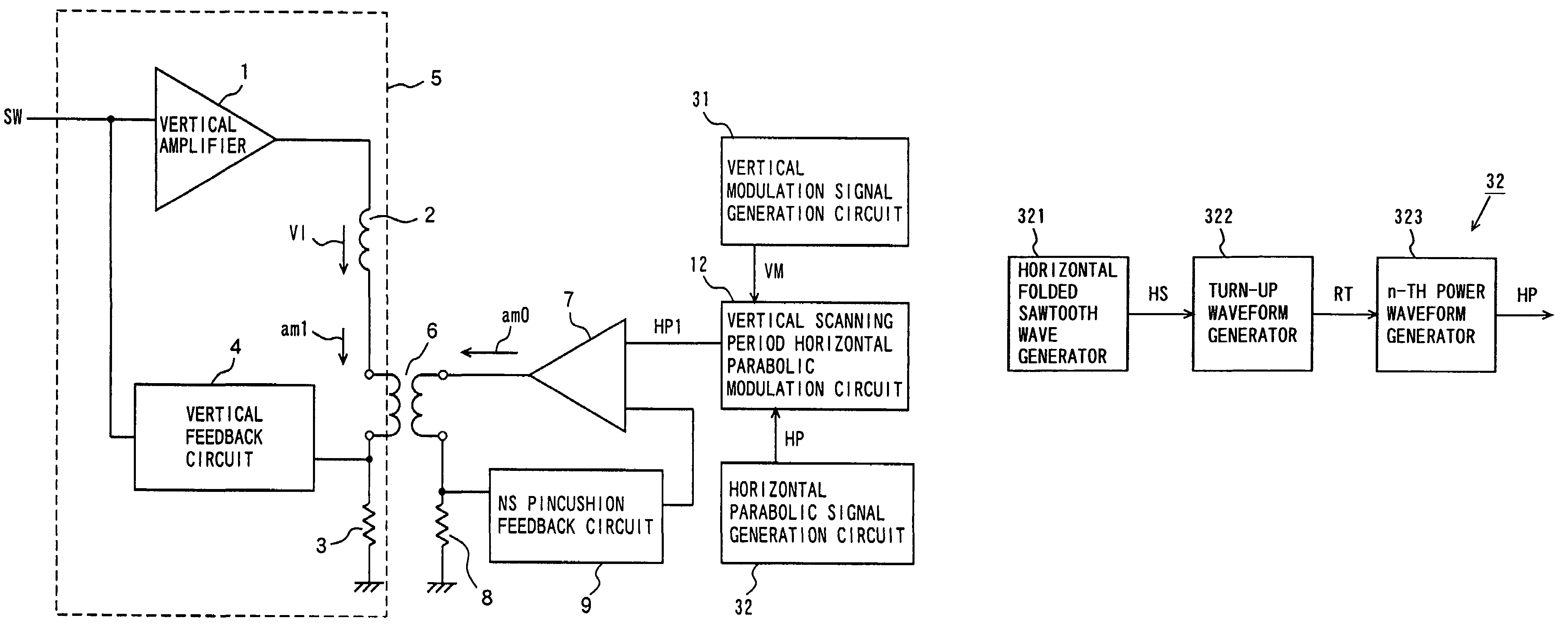
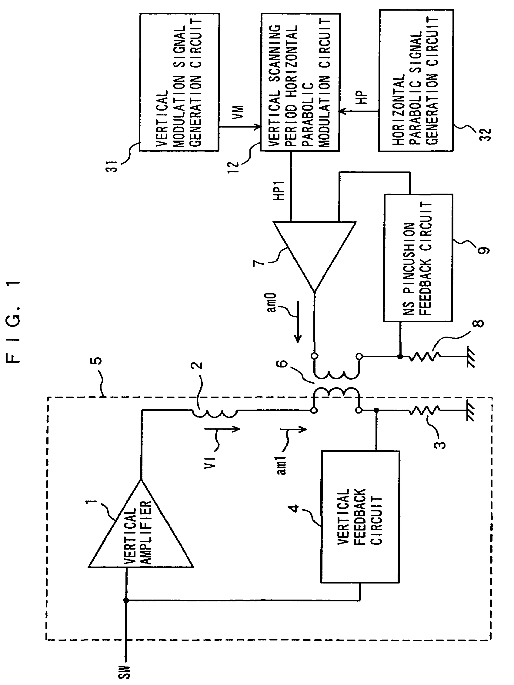
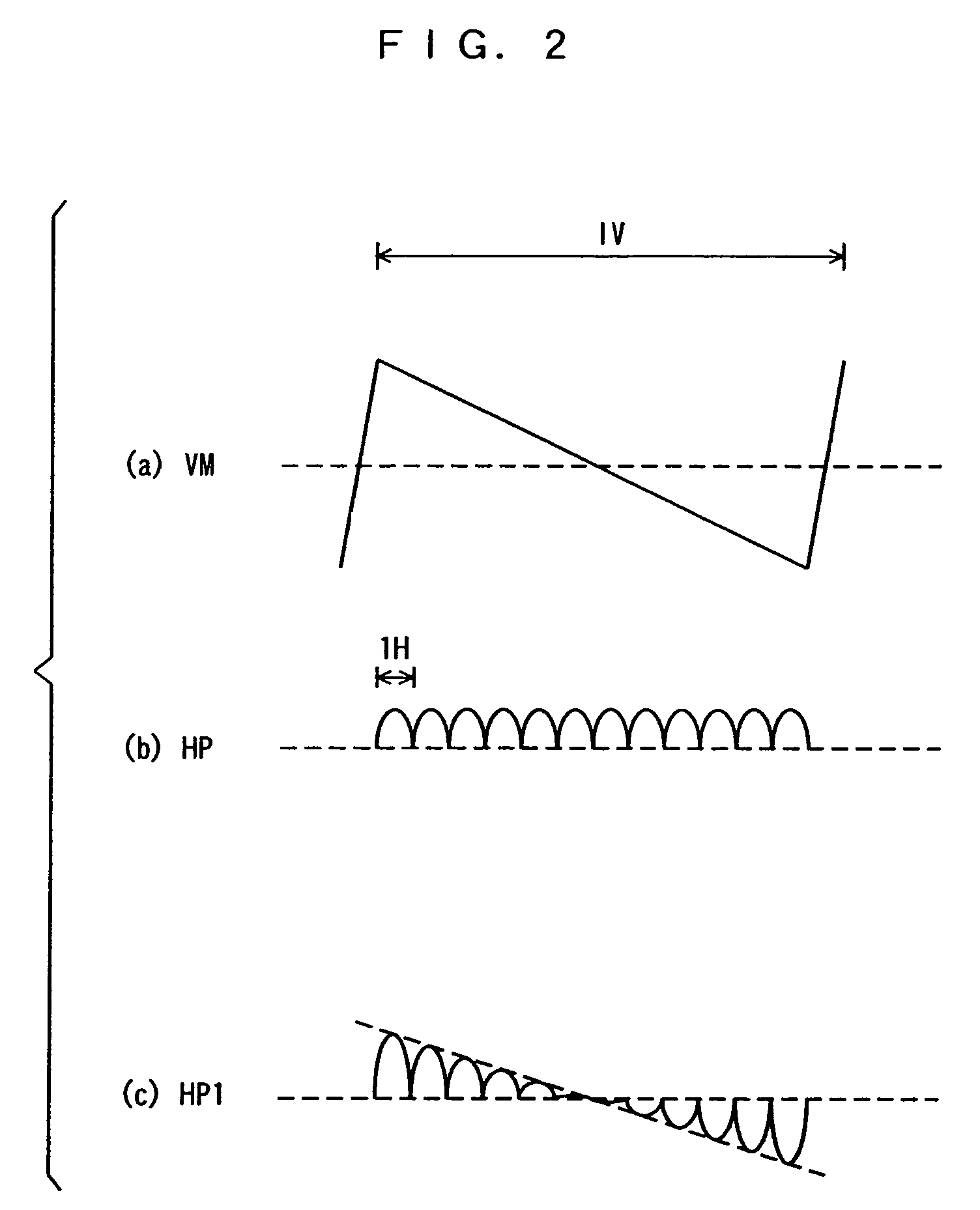
[0116]FIG. 1 is a block diagram showing the configuration of a vertical deflection apparatus in a first embodiment of the present invention. FIG. 2 is a waveform diagram showing signals of respective units in the vertical deflection apparatus shown in FIG. 1. In FIG. 2, V indicates a vertical scanning period, and H indicates a horizontal scanning period.

[0117]In the vertical deflection apparatus shown in FIG. 1, a vertical amplifier 1, a vertical deflection coil 2, a vertical current detection resistor 3, a vertical feedback circuit 4, and a secondary winding of a transformer 6 constitute a vertical output circuit 5. A sawtooth voltage SW, which changes in the vertical scanning period, is fed to an input terminal of the vertical amplifier 1. The vertical deflection coil 2, the secondary winding of the transformer 6, and the vertical current detection resistor 3 are connected in series between an output terminal of the vertical amplifier 1 and a ground termi...

second embodiment

[0157](2) Second Embodiment

[0158]FIG. 10 is a block diagram showing the configuration of a vertical deflection apparatus in a second embodiment of the present invention. The vertical deflection apparatus in the present embodiment has a configuration for power saving.

[0159]In the vertical deflection apparatus shown in FIG. 10, a vertical blanking circuit 35 is further added to the configuration of the vertical deflection apparatus shown in FIG. 1. The vertical blanking circuit 35 corresponds to a blanking circuit.

[0160]A vertical blanking signal VB and a horizontal parabolic signal HP from a horizontal parabolic signal generation circuit 32 are fed to the vertical blanking circuit 35. The vertical blanking circuit 35 sets the level of the horizontal parabolic signal HP in a vertical blanking interval to zero on the basis of the vertical blanking signal VB, to generate a horizontal parabolic signal HPb whose level in the vertical blanking interval is zero (hereinafter referred to as a...

third embodiment

[0168](3) Third Embodiment

[0169]FIG. 12 is a block diagram showing the configuration of a vertical deflection apparatus in a third embodiment of the present invention.

[0170]In the vertical deflection apparatus shown in FIG. 12, a vertical amplifier 1, a vertical deflection coil 2, a vertical current detection resistor 3, a vertical feedback circuit 4, and a secondary winding of a transformer 6 constitute a vertical output circuit 5. A sawtooth voltage SW, which changes in a vertical scanning period, is fed to an input terminal of the vertical amplifier 1. The vertical deflection coil 2, the secondary winding of the transformer 6, and the vertical current detection resistor 3 are connected in series between an output terminal of the vertical amplifier 1 and a ground terminal. A node of the secondary winding of the transformer 6 and the vertical current detection resistor 3 is connected to an input terminal of the vertical amplifier 1 through the vertical feedback circuit 4.

[0171]An o...


PUM


Abstract

A vertical deflection apparatus supplies a vertical deflection current to a vertical deflection coil to deflect an electron beam in the vertical direction of a screen. The apparatus includes: a vertical deflection current output circuit that outputs a vertical deflection current; a correction circuit that outputs a correction signal periodically changing in a parabolic shape in a horizontal scanning period to correct a north-south pincushion distortion; a modulation circuit that modulates the phase of the correction signal output from the correction circuit in a vertical scanning period; and a superimposition device that superimposes a correction current based on an output signal of the modulation circuit on the vertical deflection current. The correction circuit includes: a folded waveform generator; a turn-up waveform generator; and a correction signal generator that generates the correction signal having a peak corresponding to a turn-up point of a turn-up waveform generated by the turn-up waveform generator.

Description

[0001]This application is a division of application Ser. No. 10 / 276,472 filed Nov. 14, 2002, entitled “Vertical Deflection Apparatus” which is now U.S. Pat. No. 6,831,427 B2, and is hereby incorporated by reference in its entirety.[0002]The present invention relates to a vertical deflection apparatus comprising a correction circuit that corrects a north-south pincushion distortion on a CRT (Cathode-Ray Tube).BACKGROUND ART[0003]In a CRT, the distance from its deflecting center point to its screen (fluorescent screen) increases toward its periphery, so that the swing of an electron beam is the largest at four corners of the screen. Consequently, a north-south (upper-lower) pincushion distortion and an east-west (right-left) pincushion distortion are generated in an image displayed on the screen of the CRT. Particularly, the north-south pincushion distortion is referred to as an NS pincushion distortion, and the east-west horizontal pincushion distortion is referred to as an EW pincus...

Claims


Application Information

Patent Timeline
Patent Type & Authority Patents(United States)
IPC IPC(8): G09G1/04H04N3/23H04N3/233
CPCH04N3/2335H04N3/23
Inventor YAMATE, KAZUNORI
Owner PANASONIC CORP
Why Eureka
Try Eureka