
Position calculation system for mobile robot and charging-stand return system and method using the same

a technology of position calculation and mobile robot, which is applied in the field of mobile robots, can solve the problem that cleaning robots cannot normally return to the charging-stand, and achieve the effect of accurately calculating the wireless signal source position, effectively returning to the charging-stand, and accurately calculating the charging-stand position

Active Publication Date: 2007-01-23
LG ELECTRONICS INC
View PDF6 Cites 27 Cited by
  • Summary
  • Abstract
  • Description
  • Claims
  • Application Information

AI Technical Summary

Benefits of technology

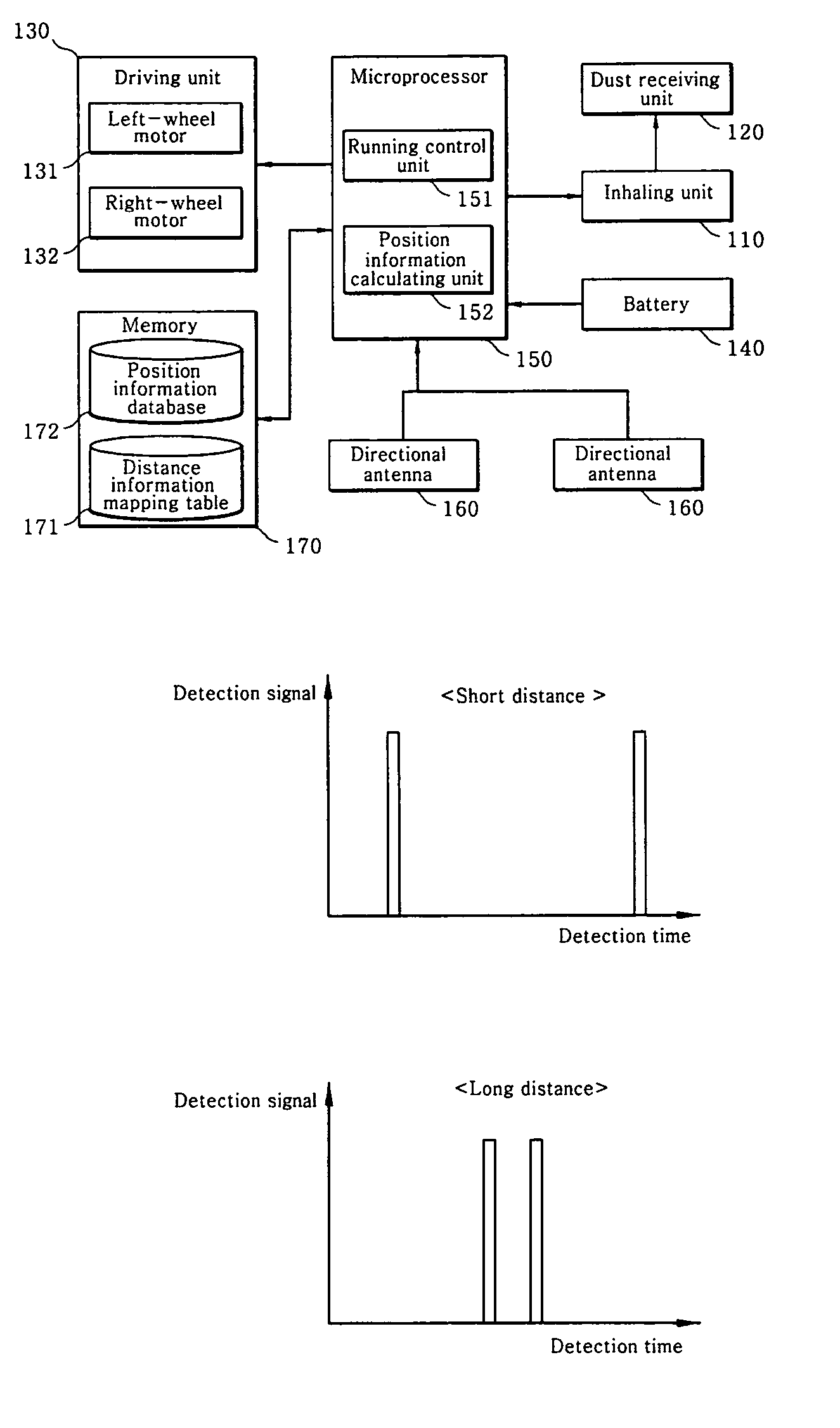
The present invention provides a position calculation system for a mobile robot that can accurately calculate the position of a wireless signal source, even if there are obstacles in the way. This system uses directional antennas on the mobile robot to detect the wireless signal and calculates the distance between the mobile robot and the wireless signal source using the time difference between the detection. The invention also provides a charging-stand return system that allows the mobile robot to effectively return to the charging-stand when its battery level is low.

Problems solved by technology

In addition, the conventional charging-stand auto-return method has problems that, in order to allow the cleaning robot to detect the artificial mark attached to the charging-stand, the charging-stand must be installed in the same area at which the cleaning robot is placed, and no obstacle between the cleaning robot and the charging-stand is present.
For example, in a case where the charging-stand is placed in a living room while the cleaning robot is placed in a different room, since the cleaning robot cannot detect the artificial mark attached to the charging-stand due to an obstacle such as a wall, it may not be possible to allow the cleaning robot to normally return to the charging-stand.

Method used


Image

  • Position calculation system for mobile robot and charging-stand return system and method using the same
  • Position calculation system for mobile robot and charging-stand return system and method using the same
  • Position calculation system for mobile robot and charging-stand return system and method using the same

Examples


Embodiment Construction

[0024]Now, preferred embodiments of the present invention will be described in detail with reference to the annexed drawings.

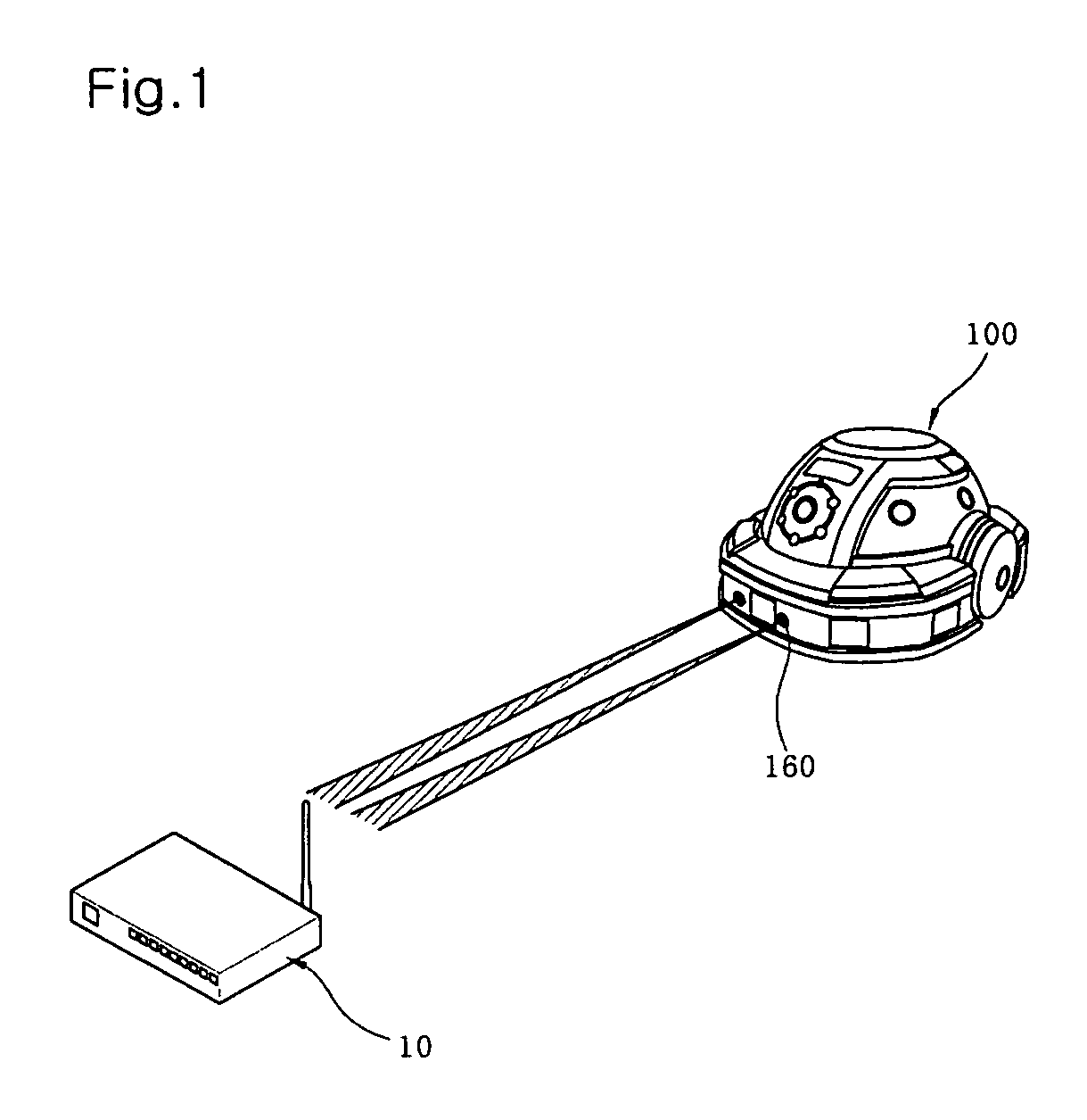
[0025]FIG. 1 is a schematic view illustrating a position calculation system for a mobile robot according to a preferred embodiment of the present invention.

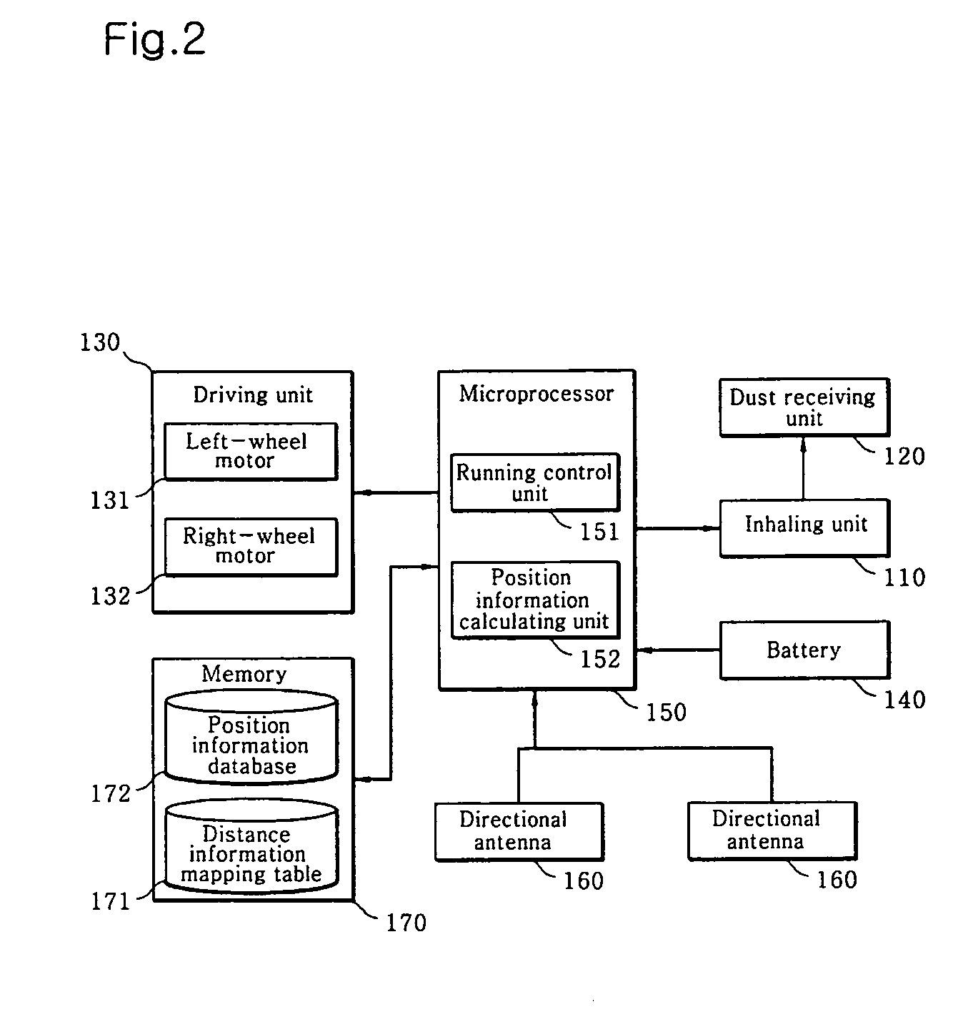
[0026]As shown in this drawing, the position calculation system for the mobile robot according to the preferred embodiment of the present invention includes a wireless signal source 10 arranged at a fixed place, for continuously or periodically outputting a wireless signal, and a mobile robot 100 which includes a plurality of directional antennas 160 for detecting the wireless signal outputted through the wireless signal source 10, wherein, the mobile robot 100 calculates a direction of the wireless signal source 10 via a rotation angle detected by the directional antenna 160, and calculates a distance separated from the wireless signal source 10 using a wireless signal detection time difference between the...


PUM


Abstract

Disclosed herein is a mobile robot which is capable of accurately calculating a position of the wireless signal source using a wireless signal, and allowing the mobile robot to accurately and rapidly return to a charging-stand using the calculated position. The position calculation system for a mobile robot includes: a wireless signal source for outputting a wireless signal continuously or periodically; and a mobile robot which includes a plurality of directional antennas for detecting the wireless signal outputted through the wireless signal source, wherein, the mobile robot calculates a direction of the wireless signal source via a rotation angle detected by the directional antennas, and calculates a distance separated from the wireless signal source using a wireless signal detection time difference between the directional antennas.

Description

BACKGROUND OF THE INVENTION[0001]1. Field of the Invention[0002]The present invention relates to a mobile robot, and more particularly to a position calculation system for a mobile robot and a charging-stand return system and method using the same, wherein, the position calculation system is capable of accurately calculating a position of a wireless signal source using a wireless signal, and the charging-stand return system is capable of allowing the mobile robot to accurately and rapidly return to the charging-stand using the calculated position.[0003]2. Description of the Related Art[0004]A robot, which has been developed as an industrial robot, has been used as a part of the factory automation. In addition, the robot has been used so as to collect or acquire required information as a substitute for a human being in an extreme situation which would be intolerable for a human being. With the application of the robots to the high-tech space development industry, a robotics field has...

Claims


Application Information

Patent Timeline
Patent Type & Authority Patents(United States)
IPC IPC(8): G05D1/00
CPCG05D1/0225G05D1/0282G05D1/0274G05D1/0272A47L9/28A47L11/00
Inventor JUNG, IL-KYUN
Owner LG ELECTRONICS INC
Learn More