Method of mitigating inner diameter reduction of welded joints

a technology of welded joints and inner diameters, which is applied in the field of tubular connections, can solve the problems of threaded connection expansion, valuable time savings, and the inner diameter of the well progressively decreases, and achieves the effects of reducing the inner diameter flash

Active Publication Date: 2007-01-30
WEATHERFORD TECH HLDG LLC
View PDF56 Cites 12 Cited by
  • Summary
  • Abstract
  • Description
  • Claims
  • Application Information

AI Technical Summary

Benefits of technology

[0015]Aspects of the present invention provide methods and apparatus for connecting two tubulars using a welding process with reduced inner diameter flash. The method includes connecting an end of a first expandable tubular to an end of a second expandable tubular using a welding process and reducing an inner diameter flash using a flash reducing device. In one embodiment, the flash reducing device is a plug disposed in the bore of the two tubulars. In another embodiment, the flash reducing device is a roller member. In yet another embodiment, the flash reducing device is a rotating cutting member.
[0016]In another aspect, a method of well completion includes connecting an end of a first expandable tubular to an end of a second expandable tubular using a welding process. The inner diameter flash is reduced before the connected tubulars are lowered into the wellbore, where a portion of the connected tubulars is expanded. The tubulars may be joined together using a welding process selected from a flash welding process, a butt welding process, a friction welding process, and combinations thereof.
[0017]In another aspect, an apparatus for connecting a first expandable tubular to a second expandable tubular is provided. The apparatus includes a housing disposable around an end of the first and second tubulars. The housing is equipped with a conductive member connected to each end of the tubulars and a translational member for moving the first tubular toward the second tubular. The apparatus further includes a flash reducing device for reducing an inner diameter flash. In one embodiment, the flash reducing device is a plug disposed in the bore of the two tubulars. In another embodiment, the flash reducing device is a roller member.

Problems solved by technology

However, one drawback of this process is that as the wellbore is extended, the inner diameter of the well progressively decreases.
Additionally, running expandable liners instead of long casing strings will result in valuable time savings.
A problem arises when the threaded connection is expanded.
However, the specifications of the threads do not take into account the expansion of the threaded connection.
For example, the tight metal-to-metal seal created between the female thread and the male thread becomes slack, thereby jeopardizing the seal at the threaded connection.
One potential problem with field joining long length tubulars is the flash or weld penetration into the inner diameter of the tubular.
The inner diameter flash represents a bore restriction that may be unacceptable for subsequent operations such as running tools into the well and expanding long sections of tubulars.
Due to its location in the connected tubular, the inner diameter flash is difficult to satisfactorily remove.
The lack of measurable flash would represent an unacceptable weld quality level.
However, scraper runs are time consuming and not cost effective.

Method used


Image

  • Method of mitigating inner diameter reduction of welded joints
  • Method of mitigating inner diameter reduction of welded joints
  • Method of mitigating inner diameter reduction of welded joints

Examples


Embodiment Construction

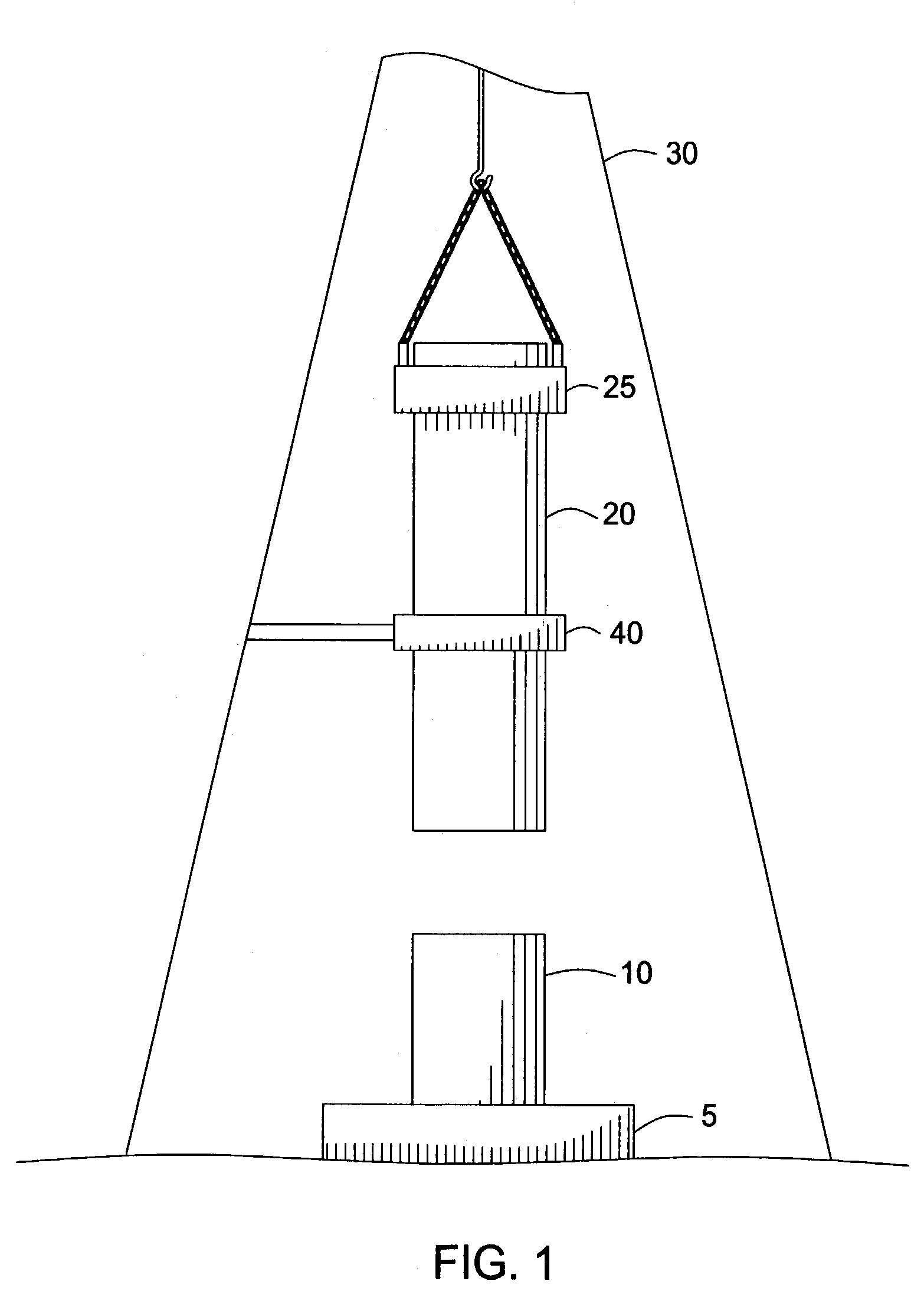
[0026]Aspects of the present invention provide apparatus and methods for reducing the inner diameter flash when two tubulars are connected using a flash welding process. As will be described in more detail below, the flash is reduced using a flash reducing device. FIG. 1 is a schematic view of a first tubular 10 ready to be joined with a second tubular 20. As shown, the first tubular 10 at least partially extends above the wellhead 5 and is held in place by a spider (not shown). The second tubular 20 is suspended above the first tubular 10 by an elevator 25 operatively connected to the rig 30. A tubular handling device 40 attached to the rig 30 may be used to help position the second tubular 20.

[0027]In one embodiment, the first and second tubulars 10, 20 are expandable tubulars to be joined and expanded downhole. Examples of expandable tubulars include expandable solid tubulars, expandable slotted tubulars, expandable screens, and combinations thereof. Further, the first and second...


PUM

PropertyMeasurementUnit
inner diameteraaaaaaaaaa
diameteraaaaaaaaaa
outer diameteraaaaaaaaaa

Abstract

Aspects of the present invention provide methods and apparatus for connecting two tubulars using a welding process with reduced inner diameter flash. The method includes connecting an end of a first expandable tubular to an end of a second expandable tubular using a welding process and reducing an inner diameter flash using a flash reducing device. In one embodiment, the flash reducing device is a plug disposed in the bore of the two tubulars. In another embodiment, the flash reducing device is a roller member. In a further embodiment, the flash reducing device is a rotating cutting member.

Description

BACKGROUND OF THE INVENTION[0001]1. Field of the Invention[0002]The present invention relates to tubular connections. More particularly, the invention relates to methods of reducing the inner diameter of a welded joint. More particularly still, the invention relates to methods of reducing the inner diameter of a welded joint between two expandable tubulars.[0003]2. Description of the Related Art[0004]In the drilling of oil and gas wells, a wellbore is formed using a drill bit that is urged downwardly at a lower end of a drill string. After drilling a predetermined depth, the drill string and bit are removed, and the wellbore is typically lined with a string of steel pipe called casing. The casing provides support to the wellbore and facilitates the isolation of certain areas of the wellbore adjacent hydrocarbon bearing formations. The casing typically extends down the wellbore from the surface of the well to a designated depth. An annular area is thus defined between the outside of ...

Claims


Application Information

Patent Timeline
Patent Type & Authority Patents(United States)
IPC IPC(8): B23K31/02E21B19/16B23K11/04B23K37/08
CPCB23K11/04B23K37/08B23K2201/10B23K2201/06B23K2101/06B23K2101/10
Inventor BADRAK, ROBERT P.
Owner WEATHERFORD TECH HLDG LLC
Why Eureka
Try Eureka