High clearance vehicle suspension with twin spindles for transferring steering torque

a high-clearance vehicle and torque transfer technology, applied in the field of suspension and steering systems, can solve the problems of increasing the complexity of the bracket, affecting the service life of the bracket, and changing so as to improve serviceability and reliability, and eliminate the steering angle and steering control problems. , the effect of reducing the cos

Active Publication Date: 2007-01-30
DEERE & CO
View PDF9 Cites 48 Cited by
  • Summary
  • Abstract
  • Description
  • Claims
  • Application Information

AI Technical Summary

Benefits of technology

[0005]It is a another object to provide an improved suspension for a high clearance vehicle which eliminates steering angle and steering control problems common with at least some of the previously available suspension systems. It is a further object to provide such a suspension which obviates need for scissors linkages or for steering cylinders that move vertically with the suspension. It is another object to provide such a suspension having a steering cylinder which is maintained generally in a consistent plane as the suspension moves over uneven terrain.
[0006]It is still another object to provide an improved suspension for a high clearance vehicle which has improved serviceability and reliability but yet is lower in cost than many previously available suspensions. It is a further object to provide such a suspension which is also more compact and lighter in weight than at least many previously available suspensions.
[0007]An independent strut suspension is described which utilizes upright twin spindles and a spindle cap linked to the spindles that translates vertically along the spindles as the suspension moves over uneven terrain. An upright strut shaft is mounted in a strut journal for axial and rotational movement with respect to the journal. A steering arm is connected for rotation about the strut shaft axis, and the strut shaft moves axially with respect to the steering arm. The upright spindles connect the steering arm and the upper mount, and a spring is supported between the upper end of the strut shaft and the upper mount and provides cushioning for the wheel support as the strut shaft moves axially in the journal. The spindle cap is rotationally fixed relative to the strut shaft and connected to the spindles for vertical movement with respect to the spindles as the strut shaft moves axially. The spindles and spindle bracket constrain the strut shaft for rotational movement with the steering arm for steering the wheel support while facilitating relative axial movement between the spindle bracket and the spindles.
[0008]The suspension eliminates scissors structures and moving cylinder supports. The torque load is carried through the spindles by allowing the suspension spindle cap casting to be linked to the spindles while still allowing the cap to translate axially along the steering spindles.
[0009]The suspension relatively light in weight and less complex and expensive than systems requiring scissors structures or steering cylinders that move with the suspension. Maintenance requirements are reduced, and the design is more compact and less subject to cylinder and hose damage. The steering cylinder can be attached at one end directly to the frame and is maintained in a plane to avoid unwanted effective cylinder length changes and steering control problems.

Problems solved by technology

Although the scissors structure functions well to keep the steering cylinder in plane during vertical motion of the strut shaft, such an assembly is relatively expensive and requires maintenance.
Although such a system can be simpler and less costly than the scissors assembly, the effective cylinder length will change with suspension travel causing undesirable changes in the steering angle and steering control problems.
In systems wherein: the cylinder mounted to move vertically with the suspension, other problems can arise such as bracket complexity and cost, cylinder clearance and cylinder hose routing requirements, and added potential for cylinder and cylinder hose damage.

Method used


Image

  • High clearance vehicle suspension with twin spindles for transferring steering torque
  • High clearance vehicle suspension with twin spindles for transferring steering torque
  • High clearance vehicle suspension with twin spindles for transferring steering torque

Examples


Embodiment Construction

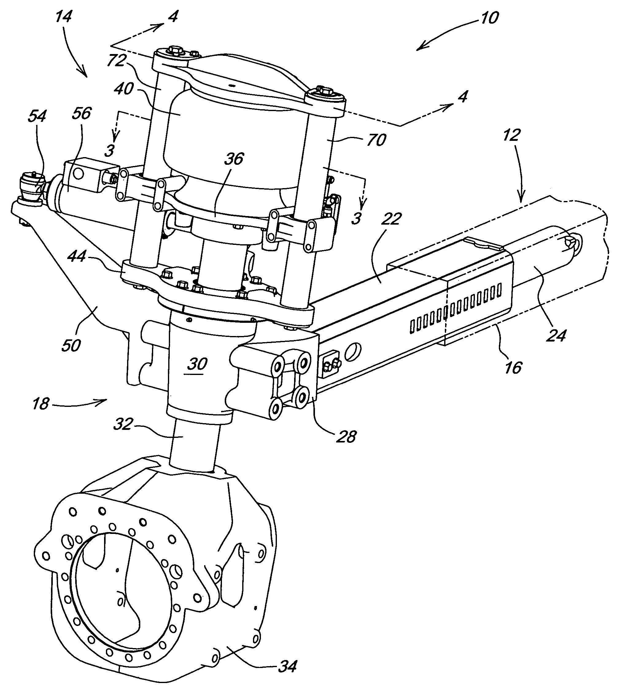
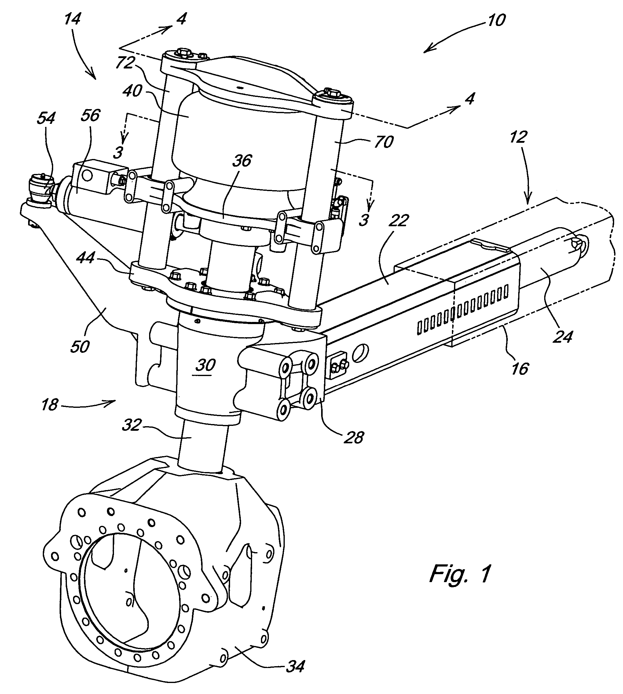
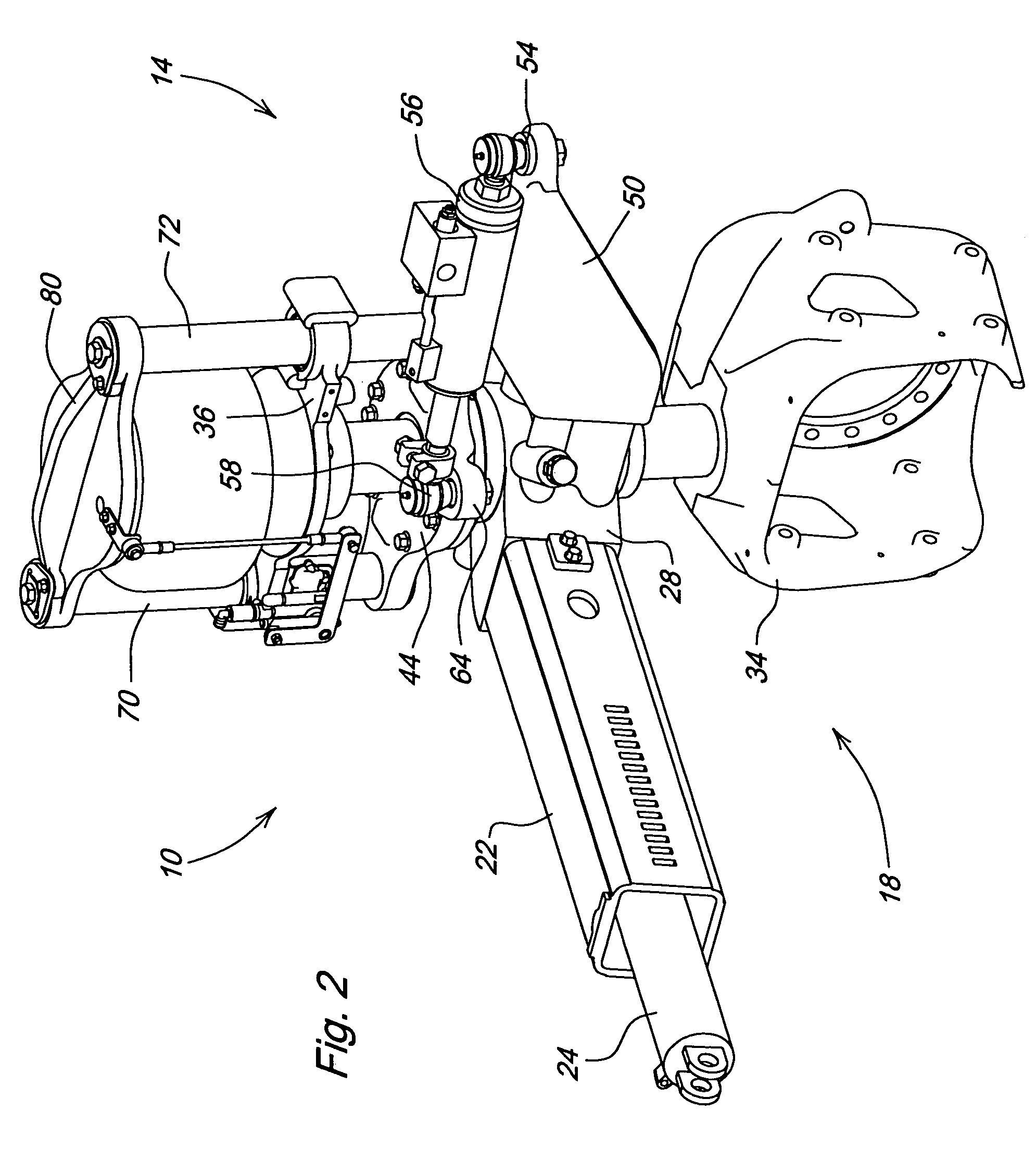
[0015]Referring now to FIG. 1, therein is shown a portion of a high clearance agricultural vehicle 10 such as a self-propelled agricultural field sprayer 10 having a main frame 12. The sprayer may be generally of the type shown and described in the aforementioned U.S. Pat. No. 5,597,172.

[0016]Transversely adjustable wheel axle assemblies, one of which is shown at 14, are slidably received in tubular frame members 16 and support a steerable suspension assembly 18. The suspension assembly 18 includes a tube 22 having an inner end slidably received by the member 16. The tube 22 is connected to a hydraulic tread adjust cylinder 24 for adjusting the vehicle tread. A knee joint 28 is connected to the outermost end of the tube 22 and includes an upright journal area 30 slidably and rotatably mounting an upright strut shaft or suspension spindle 32 having a shaft axis 32a (FIG. 4). The lower end of the strut shaft 32 is fixed to a wheel support and motor housing 34 which carries a hydraulic...


PUM


Abstract

An independent strut suspension utilizes upright twin spindles and a spindle cap linked to the spindles that translates vertically along the spindles as the suspension moves over uneven terrain. An upright strut shaft is mounted in a strut journal for axial and rotational movement with respect to the journal. A steering arm is connected for rotation about the strut shaft axis, and the strut shaft moves axially with respect to the steering arm as the frame moves over the uneven terrain. The upright spindles connect the steering arm and the upper mount, and a spring is supported between the upper end of the strut shaft and the upper mount and provides cushioning for the wheel support as the strut shaft moves axially in the journal.

Description

FIELD OF THE INVENTION[0001]The present invention relates generally to agricultural high clearance vehicles and, more specifically, to suspension and steering systems for implements such as self-propelled sprayers.BACKGROUND OF THE INVENTION[0002]Suspensions for high clearance agricultural vehicles such as the John Deere 4720 Sprayer utilize a linkage to translate torque from a steering cylinder input to the suspension spindle. Such a linkage is shown, for example, in commonly assigned U.S. Pat. No. 5,597,172 and includes a pneumatic spring supported above a strut shaft which is received within a strut journal connected to an adjustable axle. A scissors assembly located above the axle maintains wheel steer while facilitating vertical movement of the strut shaft within the journal. On non-steerable wheels, the lower end of the scissors assembly is connected to the journal to maintain a preselected wheel orientation. For steerable wheels, the lower end of the scissors assembly is conn...

Claims


Application Information

Patent Timeline
Patent Type & Authority Patents(United States)
IPC IPC(8): B60G3/01
CPCB60B35/001B62D49/0678B60B35/1054B60B35/109B60G3/01B60G11/27B62D7/06B60B35/008B60G2200/44B60G2202/413B60G2204/126B60G2204/15B60G2204/4232B60G2204/4502B60G2300/083B60G2300/40B60Y2200/22
Inventor WUBBEN, THOMAS MARKMAIWALD, MARVIN ANTHONYCARLSON, BRANDON CYANDERSON, JACK CONANBRETT, WILLIAM ALLEN
Owner DEERE & CO
Why Eureka
Try Eureka